The assumptions of the Lumped Mass model are:
1.a plane outline, a slope profile similar to a broken line consisting of straight segments;
2.point block and negligible air resistance.
In this case the trajectory of the block can be determined using the equations of the motion of a body
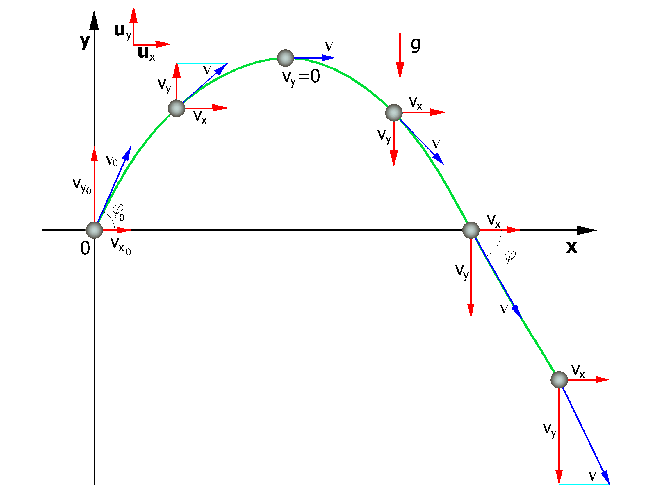
The motion is characterized by a constant acceleration a=g=-guy and the initial conditions are v=v0 at time t=0, the moment of launch.
From the definition of acceleration in plane motion we obtain the following relationship:
like
![]()
the speeds of the motions projected on the axes are:
![]()
![]()
Referring to the same system of orthogonal Cartesian axes the hourly laws of the projected motions are:
|
(1) |
where:
vx horizontal component of the block speed;
vy vertical component of the block speed;
t time;
g acceleration of gravity;
x0 abscissa of the point where block detaches from the slope or bumps in the fall motion;
y0 ordinate of the point where the block is detached from the slope or bumps in the fall motion.
Along the x-axis the motion is uniform, along the y-axis uniformly accelerated.
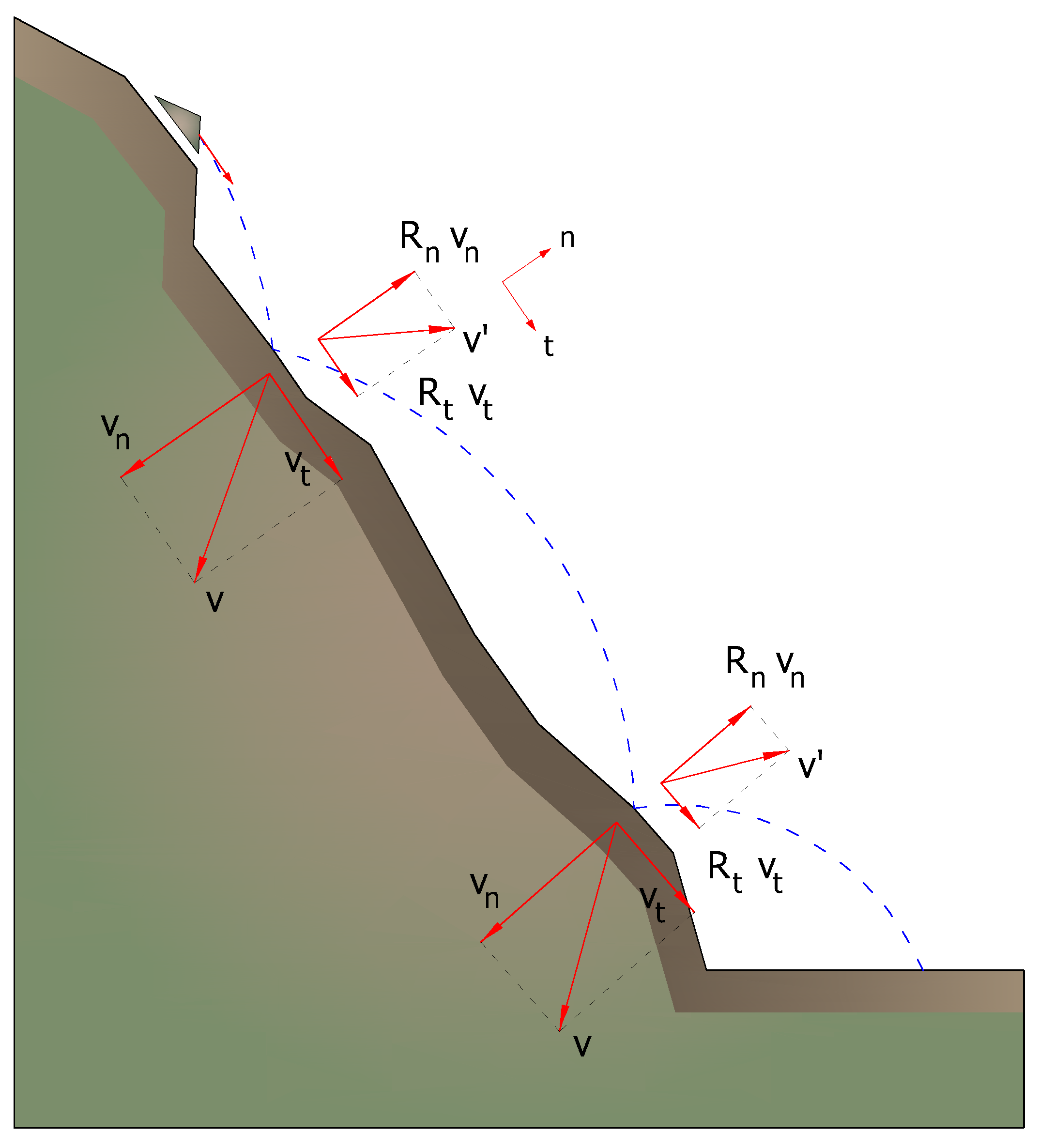
In this way the trajectory of the motion of the block is composed of a series of parabolas drawn between the point where the detachment occurs and the point where the block hits the slope for the first time, in the initial phase of the motion, and between two subsequent points of impact on the slope, or at the foot, afterwards, until the end point of arrest.
The coordinates of the points of impact and the components of the velocity are determined by solving the system between equation (1) and the equation of the straight lines which representing the slope profile.
In practice, one proceeds from the point where the block is detached and solve this system of equations by considering from time to time the different equations of the straight lines that contain the successive segments of the broken line up until find the coordinates of a point, impact point, which belongs to the parabola representing the trajectory and falls within one of the segments of the broken line and is therefore also a point of the slope.
This point represents the first point of impact of the block on the slope. The procedure is repeated starting from this point to determine the next arc of the trajectory and a new point of impact.
The loss of kinetic energy due to friction and impact can be modeled by reducing the speed of the falling block each time it hits the slope.
In particular, indicating with vn and vt the components (normal and tangential) of the velocity before the impact, after the impact v'n, v’t can be calculated by means of the relations:
![]()
Rn and Rt are called variable coefficients of restitution in the interval 0-1
|
© 2022 Geostru Software