This command opens a window in which the main parameters of the project can be given.
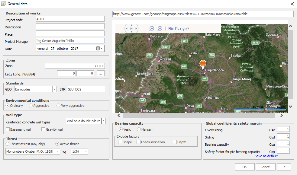
Works description
This field is intended for a synthetic description of the project.
Wall Type
In this pane it is possible to specify the type of wall by selecting from the drop down list and check boxes.
Gravity walls For Gravity walls, the program reports the results of thrust calculation and verifies slide, overturning, and limit load. Moreover it performs verification of cohesion of stem to footing joint. The latter is performed to check that the section under consideration does not generate traction but only compression tension. Such verification is presented in the report.
Head wall For for fixed head wall calculation, it is advisable to select thrust at rest (Ko) and to apply a low value for passive thrust contribution (min. 1%). The program reports soil pressure, that will have a nearly constant value.
|
Thrust
This pane is used to determine a number of factors and methods in the calculation of soil thrust either at rest (i.e. for fixed head supports) or active.
For Active thrust it is possible to opt either for Rankine's method - valid for horizontal backfill with no soil/wall friction (δ=0), or Mononobe & Okabe' s method - valid for seismic condition - based on Coulomb's non seismic condition theory. For passive thrust on downhill terrain the actually applied percentage thrust can be specified. The program only calculates passive thrust on terrain downhill of the wall footing and not on the soil covering it (See Fill pane).
In the evaluation of increase in thrust due to seismic action, the user is requested to specify the point of applicatin of such increment on the stem either at 1/3,or 2/3 of H, considering seismic thrust diagram as a triangle or as a constant on stem height at 1/2 H.
Global safety margin coefficients
Safety factor coefficients for slide, overturn and limit load can be specified here and can if required be saved as predefined in other projects.
© Geostru