Eurocode 2 rules (§6.2) for the shear, applied in the previous paragraph to the predefined sections, shall apply only to the uniaxial stress perpendicular to the neutral axis of a section of the beam subject to bending also uniaxial.
In current design applications, however, the checks of reinforced concrete columns must always be conducted in biaxial bending with axial load and in the presence of both components of the shear referring, in general, the principal axes of inertia of the section of concrete only. Capacity design of columns in seismic zones requires a considerable increase of the shear strength that can become a critical element in the design.
While for biaxial bending Eurocodes provide two types of approximate solutions in the case of biaxial shear is not given any indication, simplified or rigorous as it is, on the possible mode of calculation. It is therefore proposed the following procedure.
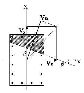
Assuming known the neutral axis at ultimate limit state, the resulting shear vector Vx+Vy is not generally orthogonal to that line. Even for the simple rectangular section of the figure it is evident that the calculation of the shear resistance conducted separately for the two acting components Vx and Vy , in addition to lead to results to the detriment of safety is conceptually incorrect because it admits the decoupling of the components Vx, Vy does not actually present in the same way as that of the components Mx, My bending moment. It therefore seems more appropriate to assume, as plane truss resistant model to shear, the plane orthogonal to the direction of the neutral axis of the section obtained from the calculation of biaxial bending in ULS. Consequently the value of the acting shear force will be constituted by the resultant VEd of the sum of the projections of the components Vx, Vy on the direction orthogonal to that of the neutral axis. Indicated with β the angle formed from the neutral axis with the x axis of inertia, the value of effective shear force to assign in the following calculation is then:
VEd = Vx sin b + Vy cos b
In this way biaxial shear problem has become an uniaxial shear calculation. Sections reported below are oriented so as to highlight the orthogonally between the neutral axis (in biaxial bending) and the direction of the acting shear VEd just defined.
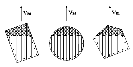
A rational approach to the problem of the evaluation of shear resistance is to divide the sections in a sufficient number of elementary strips (as shown above) plotted parallel to the direction of the shear VEd and consider the shear strength as the sum of the individual elementary strips. Each strip is considered in the same way as a rectangular section whose resistance can be evaluated based with the relationships (6.8)-(6.9) EC2 below reformulated with reference to the generic strip and assuming the stirrups always orthogonal to the beam axis (α = 90 °):
VRsd i = zi · Asw i /s · fywd cotθ (1)
VRcd i = zi · bi · ac · f’cd sinθ · cosθ (2)
where:
zi effective inner lever arm of strip i (to each zi corresponds a di value)
Asw i portion of the area of the stirrups engaged in the single strip i
s pitch of stirrups
fywd yield strength of shear reinforcement
f’cd reduced compressive strength of concrete (v1 · fcd);
acw = 1 factor for considering stress conditions in compression chord
θ inclination of concrete struts (the same for all strips).
So that each strip could represent the projection (on the cross section) of an elementary isostatic truss is necessary that its two extremes fall respectively in the current compressed strut (compressed area of the section due to the bending) and in the tensile current formed by the longitudinal bar placed along the perimeter. To meet the first condition we exclude strips that do not intersect neutral axis. The second condition may be satisfied if the longitudinal bars are sufficiently distributed along the perimeter of the section (tubular reinforcement). For columns in seismic zones you can consider this condition always satisfied because of the high values of the minimum reinforcement (ρ ≥ 1%) which involve small distances between the bars (EC8 provides, also, a distance ≤ 15 cm on high ductility DCH and ≤ 20 cm on mean ductility DCM). In not seismic zones the designer can meet this requirement with an appropriate distribution of the longitudinal bars.
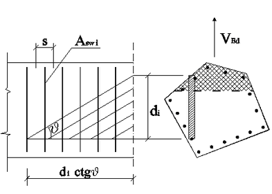
On the basis of the above assumptions the present figure shows the longitudinal section of the truss corresponding to the generic elementary resistant strut with an effective inner lever arm equal to zi and with an effective depth equal to di. In order to fully assess the shear resistance expressed by (1) remains to be defined Asw,i ie the cross sectional area of the stirrups pertaining to the elementary strut. In (1) it is evident that such resistance is directly proportional to the height of the effective inner lever arm zi, then it is logical to assume:
Asw i = zi / Szi · Asw,i
As a result the shear resistances, this time referring to the entire section, become:
VRsd = (Szi2 / Szi) Asw /s · fyd · cotθ (3)
VRcd = S zi · bi) · ac · f’cd sinq · cosθ (4)
§6.2.3(3) EC2 states that the shear resistance should be taken as the lesser of the two.
Equations (3) and (4) are equivalent to the corresponding EC2 formulas (6.8) and (6.9) provided to set:
zeff = Szi2 / Szi
deff · bw, eff = S (di · bi) = Aeff
bw, eff = Aeff / deff
The effective values bw eff , zeff, deff thus obtained define, for any form of section, width and depth of an equivalent rectangular section for the purposes of shear resistance. These dimensions allow, i.e., to use the same shear verification check illustrated for the predefined sections in uniaxial shear:
VRd, s = zeff ⋅ Asw/s ⋅ fywd ⋅ cotθ
VRd, max = zeff ⋅ bw, eff ⋅αcw ⋅f’cd ⋅ cotθ /(1 + cot2 θ)