From the results of the numerical simulation of the boulder impact on a rockfall embankment we obtain:
Ek (impact energy)
Vk (impact kinetic velocity)
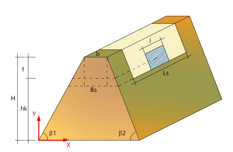
hk (impact height)
Known the volume of boulder that comes off, it can be determined:
1.The side of the footprint on the rockfall embankment (it is assumed that the boulder is contained in a cube of side "l"): l=(boulder mass)^0.3333
2.equivalent spherical radius: r=[3*boulder mass/(4*PI())]^0.3333
Other boulder data:
Specific weight. [kN/m^3] (specific weight)
mass=[(Specific weight)*boulder volume]/ gravity acceleration
Unlike elastic rockfall barriers, an embankment dissipates the impact kinetic energy of the boulder through the work that the boulder itself must make to penetrate the soil structure. It should be then calculated the penetration depth of the rock block and verified that it is less than the thickness of the work. Otherwise the artifact should be considered undersized. The depth of penetration is assessed with the relationship of Kar (1978), in the case of direct impact with the earthy material.
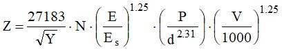
E=Block elastic modulus [kJ]
Es=Steel elastic modulus [kJ]
Y=Soil compressive strength [kPa]
N=Boulder form factor (1 for sharp objects, 0.72 for flat objects)
V= velocity impact of the boulder [m/s]
d= equivalent spherical radius [cm]
P= boulder weight [kg]
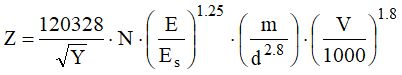
The penetration depth is therefore:
![]()
![]()
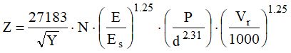
In practice, given the dual possible solution, it must be taken into consideration the higher value, and should be verified that the relevant condition z/d is respected. Otherwise it will be assumed as a valid result the other calculated value. If the embankment is supported upstream by a wall or by gabions the expression of Z must be rewritten in the following way:
If the calculation of Z appears that the boulder penetrates a depth grater than the thickness of the wall or gabions, it will be necessary to assess the residual velocity of the block as follows:
![]()
with
V = impact velocity of the boulder
Vm = minimum velocity necessary to cross the wall or the gabions, assessable by setting the value of the thickness of the wall in place of the parameter z (depending on the z/d resulting ratio), thus determining Z and resolving the expression with respect to V.
Only then we can get Z by the following expression (by replacing V with Vr ).
Calculation of the impact force
Hypothesis:
The elasto-plastic behavior of the soil constituting the embankment and of a variable dynamic load in time.
The maximum impact force generated by the boulder can be calculated by the report of McCarty and Carden (1962)
![]()
Fmax= impact force in [kgf]
K= constant usually set equal to 2.022
m= boulder mass [kg]
V = impact velocity of the boulder [m/s]
T = impact duration [s]
To determine T we can use the expression:
![]()
with
z= depth of penetration of the boulder [m]
V= impact velocity of the boulder [m/s]
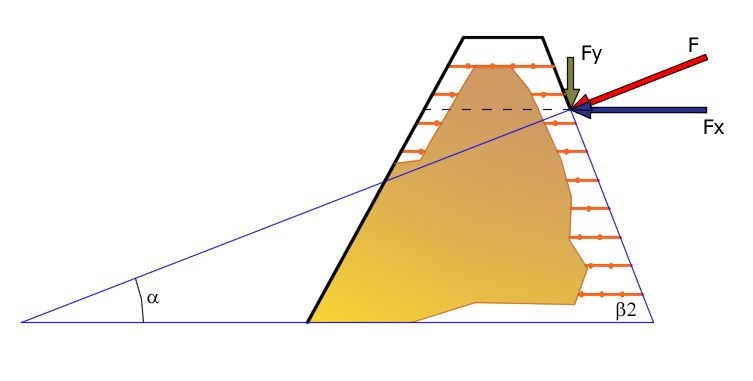
Sliding verification
Assuming that the boulder affects almost at right angles to the facade, the impact force can be broken down into two orthogonal directions defined by the reference system fixed in advance.
The incidence angle that the direction of the impact force forms with the axis of x is obtained by the rule:
![]()
where :
β2 is the angle of inclination of the upstream face of the embankment.
![]()
![]()
Known the geometry of the work is necessary to assess the weight of the embankment portion that opposes the sliding. The length of the sliding plane is determined by the relation:
![]()
With l side of the footprint on the rockfall embankment
The width of the sliding plane is determined by:
![]()
The weight of the embankment portion that opposes the sliding will be:
![]()
It must be verified that the horizontal force due to the impact of the boulder is countered with an adequate factor of safety by the friction force.
To evaluate the cohesive and frictional component that acts on the sliding surface, the following relation is applied:
![]()
C= cohesion of the fill [kN/m2]
Pr= tensile strength of the reinforcement [kN]
A= Area of the reinforcement element [m2]
φ= internal friction angle of the fill
θ= can be assumed 45+ φ/2
β= coefficient that takes account of the dilatancy [0.2-0.4]
Pr replaces the Tallow and A the spacing of the reinforcements
Replacing all the values we get:
![]()
![]()
The resistant components will be
![]() frictional component
frictional component
![]() cohesive component
cohesive component
The total resistance is the sum of the two resistance components
![]()
The verification is performed after determining the safety factor
![]()