The position of the reinforcements can be defined by points in the table by entering the coordinates X, Y with respect to the Cartesian reference system represented in the figure below.
To facilitate the reinforcements positioning it is possible to proceed with the automatic generation assigning the following geometrical characteristics:
•Initial position Yi
•Final position Yf
•Spacing h
•Bending length LRIP
•Front length Lf
•Total length Lt.
It is possible to insert the distance between the reinforcements and their type from Reinforcement typology archive.
After the input a double command must be performed:
- "Generate" calculates the insertion position of the reinforcements represented by a colored dot
- "Apply" makes the dot disappear and shows the graphical representation of the chosen reinforcements instead.
The table will contain all the variables useful for the calculation or verification of reinforcements, the user may at any time modify confirming the change with the command "Apply".
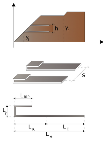
Definition of geometric parameters of the reinforcements
The analysis is performed always for one linear meter of thickness.
|
© GeoStru