The verification criterion of artificial dams works described bellow is valid for works with an embankment height smaller than 15 meters.
From a static point of view, a global judgment on the stability of the work can be inferred from an approximated procedure that divides the dam into two parts: heel and toe (upstream and downstream), to be examined separately. The subdivision is shown in the diagram of Figure 1: the RMN area is divided by the back part MNS from a vertical plane MN.
In this way, the problem is divided into two partial problems which will be solved referring to the dam thickness unit.
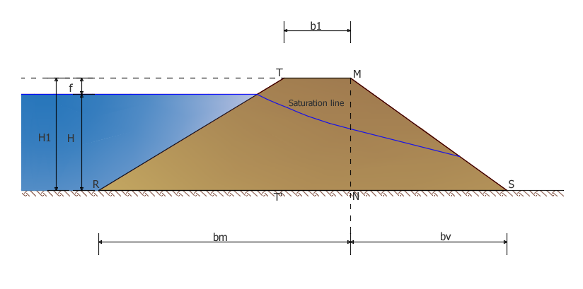
Figure 1
The toe part (downstream) MNS acts as a support of the upstream part pushed by the water: the resisting force that opposes the thrust transmitted from the heel (upstream) part manifests, at each elevation, as a shearing effort acting along the base horizontal section (most stressed section).
The verification conditions must be met for: full tank, empty tank, rapid emptied tank.
FULL TANK
The verification condition is expressed by inequality:
Tv ≤ Rv
Tv= S+Fo+Fv+Fs+FT represents the total shearing effort on the base NS and consists of the following actions:
S hydrostatic thrust invased water
FO horizontal seismic action of the structural mass
FV hertical seismic action of the structural mass
FS inertial action invased water
FT upstream embankment thrust of the MN section
Rv represents the resistance that the material is capable of developing and it consists of a frictional component and a cohesive component:
Rv=Pv (γs)·tanφ+c’·bv
Pv resultant from the vertical actions, in function of γs
c’ cohesion
EMPTY TANK
Total shearing effort Tm acting on the base section is given by the relationship:
Tm=Fo+Fv+FT
Resistance is expressed by:
Rm=Pm (γa)·tanφ+c’·bv
Pm represents the resultant of the vertical actions, function of γa
RAPID EMPTIED TANK
In this situation, there is suddenly a lack of the support action exerted by the hydrostatic thrust against the upstream facing, while the dam’s body which did not have time to drain by seepage, remains soaked with water. The total shering effort Tm acting on the base section of the upstream side is defined as:
Tm=[0.5·γS·H21·KA+0.5·γW·(2/3·H)2+kh·A(RTMSR)·γg]
The resistance Rm is expressed by the formula:
Rm=Pm (γg)·tanφ
Pm represents the resultant of vertical actions, in function of γg
The hydraulic calculation of an earth dam concerns three issues: identification of the “saturation line”, calculation of the flow rate and piping check.
The saturation line represents the highest flow line. Below all the points of the saturation line the material is saturated with water and it is under hydrostatic conditions, while above it there is a lack of pression.
It’s a convex curve upwards and can be determined graphically as shown in Figure 2.
In order to estimate the flow rate by unit of embankment thickness it is necessary to know the value of the average length of the seepage path. For this purpose, refer to the empirical relationships available in technical literature.
Through this magnitude it is possible to quantify the flow rate with the following relation:
Q=4/9·(k·H2/L)
where:
k is the geometric average of the two coefficients ko kv , ideal permeability coefficient, constant in all directions
L is the average length of the seepage route
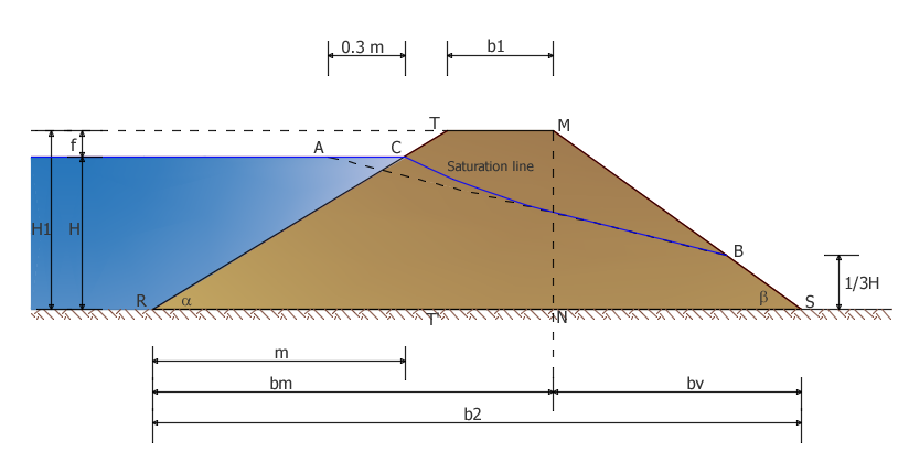
Figure 2
Piping check is made by using the empirical relation of Bligh:
La > cm·H
where:
La perimeter development of the foundation profile
cm Critical drag ratio, it depends on the nature of the soil, it can assume values between a maximum of 20 for superfine inconsistent material and a minimun of 4 for very hard and compact clays.
© Geostru