The environment for the micropiles input management is the following:
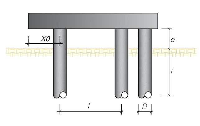
Reference diagram for the definition of the micropiles geometry
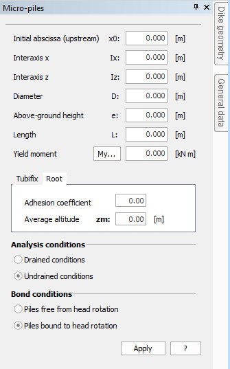
Environment for the insertion of the micropiles data
The data to be entered are the following:
•Initial abscissa (x0):
It is the abscissa in whose correspondence the micropile must be inserted. It is inserted starting from upstream (the thrusting side) and is expressed in m;
•Spacing distance x (Ix):
It is the spacing distance between the piles, measured between the geometrical barycentre of the sections associated to the piles, in a horizontal direction (the direction contained in the board plane). It is expressed in m;
•Spacing distance z (Iz):
It is the spacing distance between the piles, measured between the geometrical barycentres of the sections associated to the piles in the direction normal to the drawing plane. It is expressed in m;
•Diameter:
It is the diameter of the micropiles used in the geotechnical calculation of the micropile (Limit load). It is expressed in m;
•Above-ground height (e):
It is the distance between the pile head and the natural surface level. In other words, it is the above-ground height of the pile. It is expressed in m;
•Length (L):
It is the working length of the pile (i.e. the length contributing to the resistance by limit load). It is expressed in m;
•Yield moment (My):
It is the yield moment of the section. Only steel is considered as reacting. It is expressed in kN per m;
•Injection type:
A necessary data for tubifix piles. It can be single or repeated;
•Menard limit pressure:
It is the limit pressure of the soil surveyed on site by means of a Menard pressure meter.
•Alpha:
It is the correction coefficient to be applied to the soil cohesion in case the micropile is a root-type pile. It is dimensionless.
•Mean level:
It is the level of the midpoint of the working length for calculating the limit load of the micropile. It is expressed in m;
•Drained conditions:
Tick off this option when you want to mould the ground as cohesive;
•Undrained conditions:
Tick off this option when you want to mould the ground as non-cohesive;
•Pile from head rotation:
Tick off this option if the boundary conditions of the pile are such as to allow the rotation of the pile head without generating additional reactions.
•Pile bound to head rotation:
Tick off this option if the boundary conditions of the pile are such as to allow the rotation of the pile head, and consequently generating embedment reactions.
© GeoStru