The end-anchored bolt is represented by a truss deformable element (Figure 32). This element behaves as a single element and the interaction with the finite element mesh is through the endpoints only. These nodes can be assigned anywhere in the structural mesh, the nodes are mapped in the finite element mesh elements. The stiffness matrix of the anchor is added to the global stiffness matrix of the structure in this way.
The d.o.f displacements of the anchored element are computed in functions of the plane element nodal displacements in which the ended anchor nodes fall:
|
(130) |
or in the condensed form:
|
(131) |
|
Fig. 32. Bolt element |
|
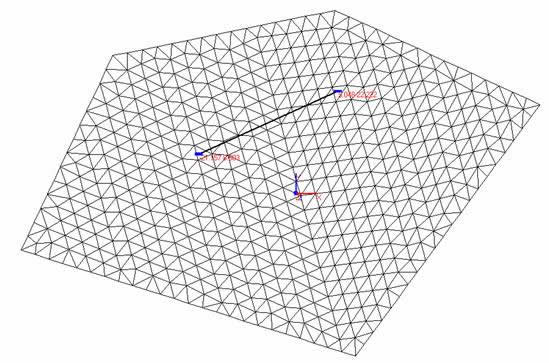
Figure 33. End anchored bolts. |
Then the anchor stiffness matrix and nodal forces vector are computed as:
|
(132) |
After this transformations the nodal force vector and stiffness matrix can be dirrectly added to the corresponding arrays of the „parent” plane elements or assembled into the structure. The nodes i and j of the truss element and their d.o.f. are not explicitly present, we can say that d.o.f. of the bar element are constrained to follow d.o.f. of the „parent” plane elements. Other situations, associted with higher order or quadrilateral elements are taken into account in the same way.
The axial force F in the anchor is calculated from the stiffness-displacement relation expressed in the local element system as:
|
(133) |
in which the displacements at nodes i and j are computed in function of the nodal displacements of the parent plane elements throughout the shape functions. For instance, considering the 3-noded triangular element (Fig. 33) the displacements at each node, in the global coordinate system are expressed as:
|
(134) |
where ![]() represents the shape functions computed for each plane element in the points associated with end anchored element. These displacements are transformed in the local coordinate system via transformation matrix (131) as:
represents the shape functions computed for each plane element in the points associated with end anchored element. These displacements are transformed in the local coordinate system via transformation matrix (131) as:
|
(135) |
Finally, with the local axial displacements computed using the above equation, the axial force along the anchor element is computed using the equation (133).
In the program have been implemented fully linear and elasto-plastic anchors. In the first case the anchor have an elastic behaviour, the failure do not occur. In the second case, failure of an anchor element occurs due to tensile yielding of the bolt material. The failure is controlled by the tensile yield strength Fy (Figure 34). When the axial force in the element reach the yield strength, that element is considered failed and no residual resistance is assumed to carryout further.
|
Fig. 34. Failure criteria. |
© GeoStru Software