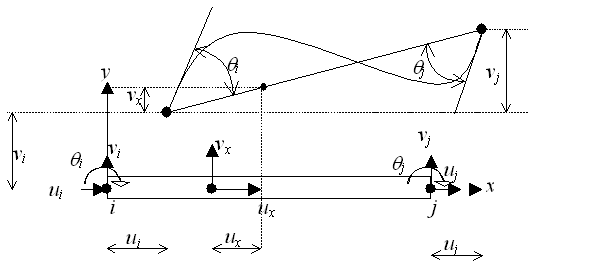
Figure 28 shows a six degree of freedom straight beam-column element. Rotation θ is assumed to be small, so that![]() . The displacement field along the element is assumed to be the following shape (a linear shape for axial displacements and third degree polynomial for transversal displacements):
. The displacement field along the element is assumed to be the following shape (a linear shape for axial displacements and third degree polynomial for transversal displacements):
|
|
(88) |
|
Fig. 28. Beam column element |
The third degree polynomial shape has been chosen for the transverse displacements since for an element loaded only at the nodes the shear forces and bending moment variation along the element is constant and linear respectively:
|
|
(89) |
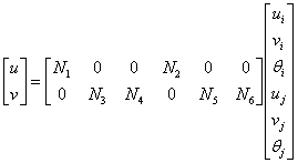
Imposing the limit conditions the displacement element field can be rewritten:
|
|
(90) |
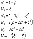
where the shape functions Ni in this case are:
|
|
(91) |
and in which ![]() . Assuming a linear distribution of the strains along the cross-section (plain section hypothesis) the strain –displacement relationship is:
. Assuming a linear distribution of the strains along the cross-section (plain section hypothesis) the strain –displacement relationship is:
|
|
(92) |
or written in the matrix form:
|
|
(93) |
or in the matrix condensation form the displacements and strains relationships can be expressed as:
|
|
(94) |
where u represents the nodal displacement vector, and B represents the strain-displacement operator:
|
|
(95) |
|
|
(96) |
|
|
(97) |
or with the following relations:
|
|
(98) |
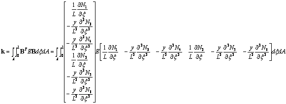
and assuming a doubly symmetric cross-sections, the element stiffness matrix can be computed as:
|
|
|
With the definition of moment of inertia and cross-sectional area:
|
|
(100) |
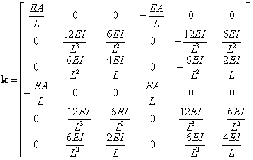
and for constant EI the element stiffness matrix given by the equation (99) is:
|
|
(101) |
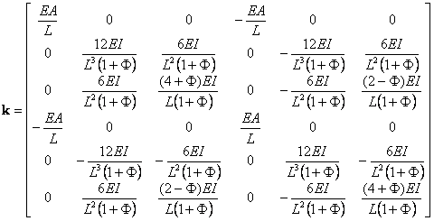
A slightly modified form of Eq. (101) is able to account for transverse shear deformation (Timoshenko beam-column).
|
|
(102) |
where ![]() , G represents the shear modulus and As the shear area, and the product GAs represents the shear rigidity.
, G represents the shear modulus and As the shear area, and the product GAs represents the shear rigidity.
The stiffness matrix if for the xy local element coordinate system oriented with the beam. If the beam is inclined at an angle β to the global coordinate axis X, the element stiffness matrix in global coordinate system is computed as:
|
|
(103) |
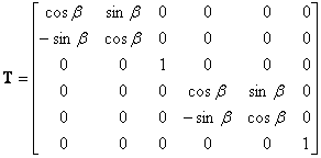
where the rotation matrix T has the following expression:
|
|
(104) |
|
© GeoStru Software

