Columns of gravel are inserted in the liquefiable layer and are usually installed in quincunx (Figure 5a), as this is the cheapest disposition available. In practice, however, are also arranged in a square mesh (Figure 5b).
|
|
a) |
b) |
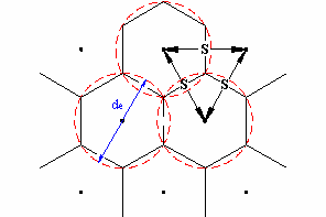
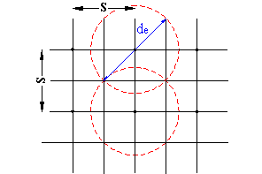
Figure 5 – Disposition of drains: a) Triangular disposition (quincunx); b) Square mesh disposition.
S indicates the spacing between the drains, while de is the equivalent diameter of drained soil cylinder
S indicates the spacing between the drains, while de is the equivalent diameter of drained soil cylinder.
In any case, the problem to be solved can be reduced to that of a soil equivalent (Figure 6), with the waterproof outer lateral surface and a central drain.
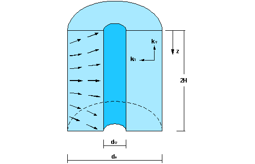
Figura 6 – Scheme of drained soil equivalent cylinder
dw = drain diameter
de = drained soil equivalent cylinder diameter
kh = permeability coefficient in horizontal direction of the soil in undisturbed conditions
kv = permeability coefficient in vertical direction of the soil in undisturbed conditions
2H = height from drain
z = relative depth
The equivalent diameter of the soil cylinder that drains de is equal to 1.05 times the spacing S of the drains if they are arranged in quincunx and equal to 1.13 S in case they have a square mesh disposition.
For drains in square mesh disposition it is possible to evaluate the spacing necessary to bring the void ratio from a value eo to a value e in an approximated way with the following expression:
![]()
Barron (1948) was the first to develop a systematic and complete approach of the problem; in it are taken as valid the assumptions of Terzaghi’s one-dimensional theory.
The average degree of consolidation Uh is calculated using the following expression:
![]()
where Th and F are equal to:
![]()
![]()
where:
mv = coefficient of volumetric compressibility
n = ratio between diameter de and diameter dw
t = 0,055 exp(0,861M) duration of the design seismic event
M = magnitude of the design seismic event
The magnitude of the design earthquake is calculated using the empirical relationship of Berardi et al.
![]()
where R is the epicentral distance in km of the design earthquake.
This report has the meaning of minimum magnitude required to produce liquefaction of recent surface saturated sand deposits and allows to work in favor of safety.
© Geostru