The indications of European legislation are found in paragraph 4.1.3 with further directions that can be found in Appendix B of Part 5 of EC8.
According to this legislation can be excluded the risk of liquefaction for saturated sandy soils that are found at depths of 15 m or when ag < 0.15 and, at the same time, the soil meets at least one of the following conditions:
• clay content greater than 20%, with plasticity index>10
• silt content greater than 10% and N1,60 > 20
• fine fraction negligible and N1,60 > 25
Generally the method is valid if N1,60 < 30. For N1,60 > 30, the soils are classified not liquefiable (clean dense granular soils). |
When none of the above conditions is met, the susceptibility to liquefaction shall be verified as minimum by generally accepted methods of the geotechnical engineering, based on correlations between in situ measurements and the critical values of cyclic shear stress that caused liquefaction during past earthquakes.
The cyclic stress ratio CSR is calculated using the simplified formula:
![]()
where S is the stratigraphic profile coefficient, defined as:
Table 5- Stratigraphic profile coefficients
Soil type |
Spectra of Type 1 S (M > 5,5) |
Spectra of Type 2 S (M ≤ 5,5) |
|---|---|---|
A |
1,00 |
1,00 |
B |
1,20 |
1,35 |
C |
1,15 |
1,50 |
D |
1,35 |
1,80 |
E |
1,40 |
1,60 |
The magnitude scaling factor MSF suggested by the legislation is Ambraseys (Table 1-method Seed Idriss).
If there is any data from the SPT tests, liquefaction resistance is calculated using Blake (1997) equation:
![]()
where (N1,60)cs is calculated using the method proposed by Youd and Idriss (1997) and recommended by NCEER:
![]()
where N1,60 is the normalization of the measured values of the index Nm (reduced by 25% for depth < 3 m) in the SPT test compared to an effective pressure of 100 KPa and a value of the ratio between the impact energy and the theoretical energy of free fall (flight) equal to 60%, ie:
![]()
![]()
![]()
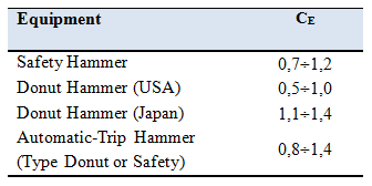
where ER is equal to (ratio of the measured energy compared to the theoretical value) x 100 and depends on the type of equipment used (Table 6).
Table 6- Drilling system efficiency
The parameters α and β, instead, depend on the fine fraction FC:
α = 0 for FC ≤ 5%
α = exp[1,76 -(190 / FC2)] for 5% < FC ≤ 35%
α = 5 for FC > 35%
β = 1,0 for FC ≤ 5%
β = [0,99 + (FC1,5 / 1000)] for 5% < FC ≤ 35%
β = 1,2 for FC > 35%
In the following cases, the soil is not susceptible to liquefaction, the program does not provide the safety factor but (--):
1.amax < 0.15 , Clay fraction > 20 and IP = > 10
2. Number of the CRR report less than zero
3. amax < 0.15 , Clay fraction > 20
4. amax < 0.15 , N1,60 > 25
If data from a static penetration test (CPT) are available, the measured tip resistance (qc) values must be normalized compared to an confinement effective pressure equal to 100 KPa and must be calculated using the following relationship:

As proposed by EC8, when data from a CPT test is available, can be used the following equation to derive the value of (N1,60)cs:
![]()
The value of the liquefaction resistance is determined by the relationship of Blake (1997). When instead is available data from refraction seismic tests, the normalized propagation velocity is calculated using the relationship proposed by of Robertson et al. (1992):
For the liquefaction resistance is used the formula of Andrus and Stokoe :
© Geostru