The LRFD approach consists in checking the following equation:
![]()
Where Q and R can represent forces, as well as stresses, deformations, displacements, etc. In this equation, Q represents an amplified value of actions, while R is a reduced value of resistances. The fundamental concept of LRFD design is expressed by the following relationship:
![]()
In which
Q : factored load
Qi : force effect
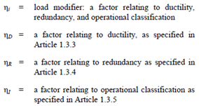
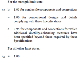
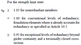
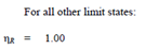
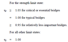
ηi : load modifier
γi : load factor
Rr : factored resistance
Rn : nominal resistance (i.e., ultimate capacity)
φ : resistance factor
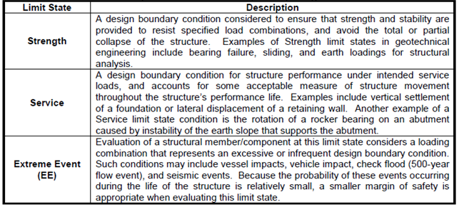
According to the LRFD approach, it is necessary to perform the verifications with reference to the following limit states:
•Strength limit state
•Service limit state
•Extreme event limit state
•Fatigue limit state
In geotechnical verifications, the 'fatigue limit state' does not need to be performed.
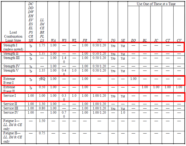
For each of these limit states, the standards identify various levels, which are indicated in the table below:
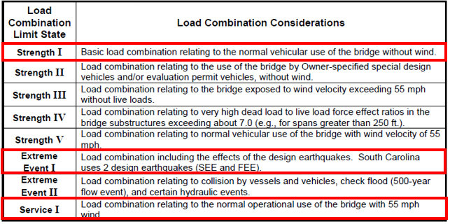
Most of these levels are to be performed only in the case of bridges subjected to specific wind conditions. The ones that need to be executed for all types of structures are those highlighted in red in the table (Strength I, Extreme I, Service I).
TYPES OF LOAD
In the LRDF approach, loads need to be amplified based on their type. Specifically, after distinguishing between permanent and transient loads, additional subcategories are identified, based on which the coefficient γi varies.
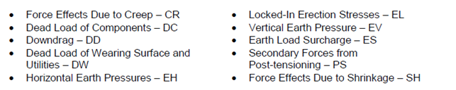
The permanent loads and their respective subcategories are as follows:
Permanent loads are present for the life of the structure and do not change over time. Permanent loads are generally very predictable. The following is a list of all loads identified by AASHTO LRFD Specifications as permanent loads:
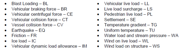
The variable loads and their respective subcategories are as follows:
Transient loads may only be present for a short amount of time, may change direction, and are generally less predictable than permanent loads. Transient loads include the following:
The values of the coefficients γi to be used are reported in the following table, depending on the type of load and the considered limit state.
The coefficients indicated in this table with the symbol γp should be taken from the following tables:
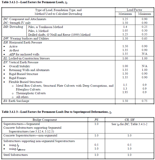
The γEQ and γse coefficients must be determined based on the specific project.
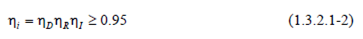
In the following it is indicated how to calculate the ηi coefficients, which depend on what value of γi is used. For loads for which a maximum value of γi is appropriate:
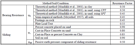
BEARING CAPACITY CALCULATION
The ultimate value of the bearing capacity is calculated as follows:

where:
φb : resistance factor
qn : nominal bearing resistance
The nominal value is calculated using the well-known trinomial formula:

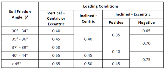
The values of the resistance factor are defined in the following table:
Alternatively, it is also possible to refer to the values indicated in the following table (valid for relative density values Dr > 35%).
|
© GeoStru