This section resides within the Foundation Pile Window and is devoted to the properties of the pile itself and contains the following entry boxes:
Description
Give textual description for this type of pile.
Type
Select from drop down list either driven or bored type of pile. See also guide tip which appears when the box is active..
Point/Tip diameter (m)
Enter pile point (lower) diameter.
Length (m)
Enter pile length (depth) of the pile measured from excavation dredge line. Please note that at least this depth must have been specified in the stratigraphy window such that the pile does not extend below the lowest layer boundary.
Protrusion at dredge (m)
Height of protrusion of top of pile over the level of excavation dredge line.
Trunk conicity %
The data to enter defines whether the pile is a conic section as opposed to cylindrical and with what angle, its diameter decreases. The value is only relevant for driven piles. Where relevant enter a percentage figure that indicated the diminution percent for each meter length. (10% indicates 10 cm./ meter). See also guide tip which appears when the box is active.
Poisson coeff. of pile tip layer(max 0.5)
Enter value of Poisson’s coefficient for the layer at which the pile tip is immersed. This is required for settlement calculation. See also guide tip which appears when the box is active.
Relative density of pile tip layer (%)
Enter value of relative density for the layer at which the pile tip is immersed. This is required for calculation of tip bearing capacity using Vesic’s method.
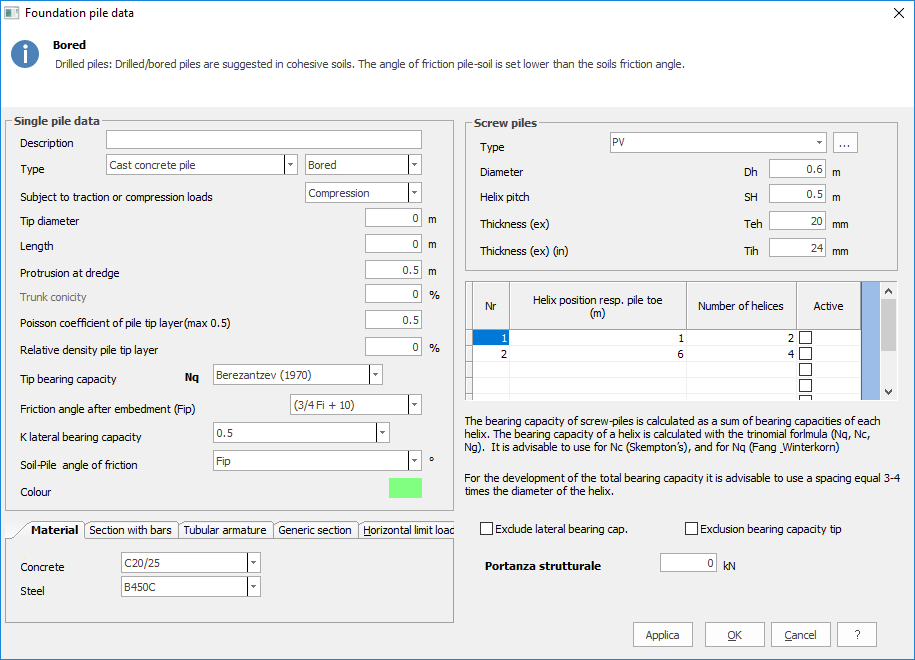
Tip bearing capacity (Nq)
Select from drop down list the author (Berezantev, Terzaghi, Janbu, Hansen e Vesic or User) of the method for computation of tip bearing capacity. (See also technical notes). If ‘user’ is selected, an additional box opens beside the list, to enable the user determined value to be entered.
Friction angle after embedment (Fip):Select the angle of friction to be used for bearing capacity when the pile is in place. For driven piles it is suggested to use ¾ the soil value increased by 10; For bored piles it is normal to diminish the soil value by 3º. See also guide tip which appears when the box is active.
K lateral bearing capacity
Select from drop down list the value to assign to coefficient K for the computation of the lateral bearing capacity of the pile. For bored piles the usual value is =1-sin(Fip); for driven piles the usual value is= 1-tan²(Fip); Value = 0.5 is common for steel piles and = 1 for prefabricated concrete or wooden piles. If ‘user’ is selected, an additional box opens beside the list, to enable the user determined value to be entered. See also guide tip which appears when the box is active.
Soil-Pile angle of friction
Select from drop down list, the value to use for delta in computation of lateral bearing capacity of the trunk of the pile. For bored piles the usual value is Fip (See above) while for driven prefabricated concrete piles, the usual value is ¾ Fip. For steel piles the usual value is 25º. See also guide tip which appears when the box is active.
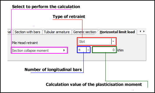
Pile Head restraint
Select from list either slot or hinge as relevant. This selection is only active if either ‘Structural computation? or ‘Limit horizontal load’ check boxes in General Data window have been selected. The specification is needed for the calculation of limit horizontal load and the plastification moment of the section.
Section collapse moment (Kg/m)
This selection is only active if either ‘Structural computation? or ‘Limit horizontal load’ check boxes in General Data window have been selected. Insert the value of plastification moment of the section. See also guide tip which appears when the box is active. Where the material properties have already been entered (Material properties in Data menu), the program is able to calculate this figure. Click in the box and then on the blue underlined text below the tip text box which reads: ‘Compute section collapse moment’. This asks for the actual number of rod armatures and then fills the result in the box.
Colour
Opens a colour palette from which the colour of the pile on the diagram may be selected.
The calculation of the horizontal limit load is subject to the calculation of the moment of rupture of the section, access the label Horizontal limit load, select the type of retraint of pile head, define the number of longitudinal bars (for sections in reinforced concrete) and click on the button Section collapse moment.
In accordance with the general rule of the Eurocodes for foundation piles, NON-dissipative behaviour was assumed.
Said ‘substantially elastic’ behaviour implies that the ultimate resistant moment (capacity) is that of ‘first yielding’, as defined in the Eurocodes themselves, i.e. as the moment indicated with M'yd = maximum resistant moment of the section in the substantially elastic field. This moment M'yd is, therefore, that calculated by the programme as the ultimate moment (= first yield moment).
Screw pile
The geometrical data of the helix plate that characterize the pile must be assigned in the field indicated with (d) in the figure (pile data).
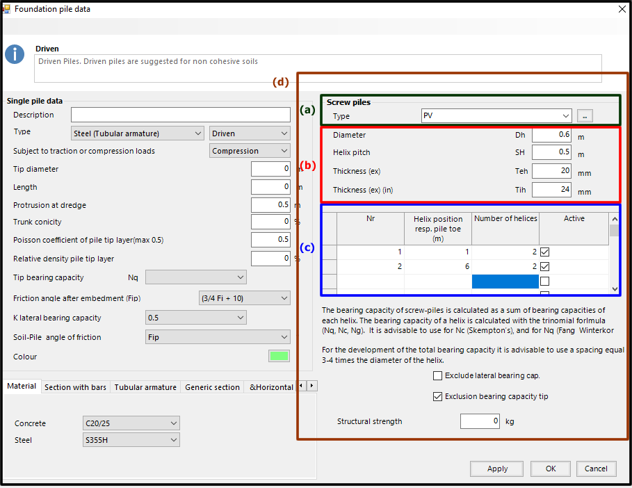
Pile data – screw pile
In the type field, (a) in the figure (pile data-screw pile), the user can associate an abbreviation to the type of pile.
In section (b) it is possible to characterize the geometry of the single helix, the references are explained in the figure (helix geometry).
In order to define the number of helix plate and their position relative to the top of the pile, it is necessary to report the data on the table highlighted by the blue box, (c) in the figure (pile data – screw pile).
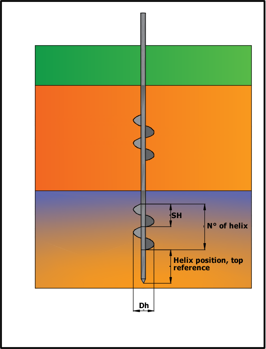
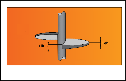
Helix geometry
© GeoStru