Screw-Piles and Helical Anchors in Soils
This Guide should be used for preliminary calculations only and applies only to the deep installation of Screw-Piles and Helical Anchors in uniform soils. It is only applicable for design when the depth (D) to the top helical plate is greater than 10 times the diameter (B) of the helical plate and the minimum depth of embedment of the helical plate is 5 ft. The methods described in this Guide provide an estimate of the ULTIMATE capacity; the Engineer must apply an appropriate Factor of Safety to obtain the ALLOWABLE capacity.
General Bearing Capacity Equation
At the present time, the design of Screw-Piles and Helical Anchors generally follows the traditional theory of General Bearing Capacity used for compression loading of foundations. Terzaghi’s general bearing capacity equation for determining ultimate bearing capacity, as given in most Foundation Engineering textbooks is often stated as:
qult = c’·Nc + γ’· D·Nq + 0.5· γ’·B·Nγ
where:
qult = Ultimate Unit Bearing Capacity
c’ = effective cohesion
q’ = effective overburden stress = γ’D
γ’ = effective unit weight of soil
D = depth
B = diameter of helix
Nc, Nq, Nγ = bearing capacity factors
Notes on use of Terzaghi’s General Bearing Capacity equation:
1. Because B is considered very small for Screw-Piles and Helical Anchors, relative to most concrete footings, some engineers choose to ignore the term 0.5γ’BNγ in design.
2. In saturated clays under compression loading, Skempton’s (1951) Bearing Capacity Factor for shallow round helical plates may also be used:
Nc=6 (1+0.2 ·D/B)< 9
3. The unit weight of the soil is the total (wet) unit weight if the helical plate is above the water table and the buoyant unit weight if the helical plate is below the water table.
4. For saturated clay soils with φ’ = 0, Nq = 1.0; For sands, Nq is a function of friction angle, φ’
5. In all cases, for both compression and tension loading, the upper limit of capacity is governed by the mechanical strength of the Screw-Pile or Helical Anchor as provided by the manufacturer.
Contribution of Shaft to Capacity
Many Screw-Piles and Helical Anchors are manufactured with square central shafts. For these piles/anchors, the contribution of the shaft to the ultimate capacity is usually ignored and the total capacity is only calculated from the bearing capacity of the helical plate(s). For Screw-Piles and Helical Anchors with round steel central shafts the shaft section between plates for multi-helix elements is ignored, but the shaft above the top plate may be included in design, at least for that section of the shaft in full contact with the soil as discussed in Section 3.
DEEP Single-Helix Screw-Piles and Helical Anchors
Deep installations of Screw-Piles and Helical Anchors are generally more common than shallow installations, provided there is sufficient soil depth to perform the installation. The reason is that higher load capacities are generally developed from a deeper installation in the same soil.
Compression Loading of Screw-Piles in CLAY
Under both compression and tension loading of deep Screw-Piles and Helical Anchors in clay, the ultimate capacity is obtained using the Total Stress Analysis (TSA) and undrained shear strength. In saturated clays with φ’ = 0 and c = su the bearing capacity equation is often give as:
QH= AH ·Nc ·su
where:
QH = Ultimate Bearing Capacity in Compression
su = undrained shear strength
Nc = Bearing Capacity Factor for clays with φ’ = 0; for round plates
AH = Effective area of the helical plate For deep installations,
Compression Loading of Screw-Piles in SAND
For deep installations of single-helix Screw-Piles and Helical Anchors in sand the ultimate capacity is obtained using the Effective Stress Analysis (ESA) from:
QH= AH ·(σ’vo ·Nq+0.5 ·γ’ ·B ·Nγ)
where:
σ’vo = vertical effective stress at the depth (D) of the helix = γ’D
Nq and Nγ = bearing capacity factors
B = Diameter of the helical plate
γ’ = effective unit weight of the soil
The bearing capacity factor Nq is usually obtained from values used for determining the end bearing capacity for deep pile foundations. There have been a number of different recommendations for estimating Nq which are available in most foundation engineering textbooks, e.g., Fang & Winterkorn 1983:
Nq = 0.5· (12·φ’)(φ’/54)
Because the area of the plate is usually small, the contribution of the “width” term (0.5·γ’·B·Nγ) to ultimate capacity is also very small and the width term is often ignored. This reduces to
QH= 0.5· AH· [σ’vo · (12·φ’)(φ’/54)]
DEEP Multi-Helix Screw-Piles and Helical Anchors
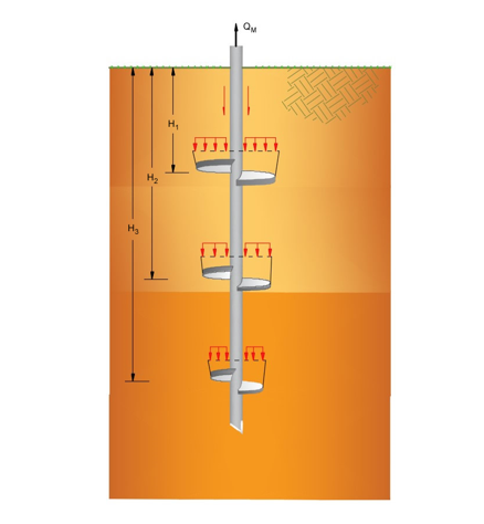
The ultimate capacity of deep multi-helix Screw-Piles and Helical Anchors depends on the geometry of the helical section, namely the size and number of helical plates and the spacing between the plates. In the U.S. most manufacturers of Screw-Piles and Helical Anchors produce elements with a helix spacing of 3 times the helix diameter. This spacing is assumed to allow individual plates to develop full capacity with no interaction between plates and the total capacity is often taken as the sum of the capacities from each plate as shown in Figure.

Development of Capacity for Multi-Helix Screw-Piles and Helical Anchors with S/D >3.
Compression and Tension Loading of Multi-Helix Screw-Piles
Ultimate capacity of multi-helix Screw-Piles in compression and Helical Anchors in tension with a helix spacing/diameter ration > 3 is often taken as the summation of the capacities of the individual plates:
QM = ΣQH
where:
QM = Total Capacity of a Multi-Helix Screw-Pile/Helical Anchor
QH = Capacity of an Individual Helix
Reference
Dr. Alan J. Lutenegger, P.E., F. ASCE for International Society for Helical Foundations (ISHF)
© GeoStru