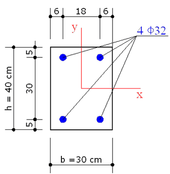
The above cross section of a column refers to Example 5.4 in /6/. C50/60 is the concrete class and S500C is the steel grade.
The concrete design strength is: fcd = αcc⋅ fck / γc = 0.85 ⋅ 50 / 1.5 = 28.3 Mpa
The steel design yield strength is: fyd = fyk/ γs = 500/1.15 = 434.8 Mpa
The authors in /6/ claim that the above reinforcement is the exact and rigorous solution to the project under the forces N= 2000 kN, Mx = 234 kNm; My = 100 kNm.
To control that statement we perform a biaxial check of the section with the given reinforcement in order to compare the capacity forces with the design ones.
In addition to the previous question we want to design shear reinforcement for a ULS biaxial shear design force Vx = 420 kN, Vy = 180 kN and compare the results with uniaxial separate checks.
INPUT DATA
Once opened a new calculation (by means the command "New" in the menu File) it is important to control if the default code setting options agree with those in the given example to compare.
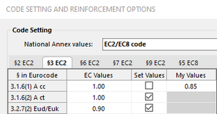
In this example we control, in particular, the parameters γc, γs , αcc. The EC2 recommended value of the last parameter αcc is 1.00 and it is to change in 0.85 as in the example. If a specific National Annex is selected no change is necessary. We left the values of the shear parameters as recommended in EC2.
In the context of this example, we could possibly modify the following option:
- The diameter of first (8 mm) and second (10 mm) diameter of stirrups
- Max personal max value of cot θ = 2.5 as usual in reinforcement shear design.
In the below General Data windows we should selected the typology "Rectangular section of column", but this special typology provides the same cover for all the bars. As in this case the covers are different for the two sides, we are forced to select the "General" typology. Then we select "Column" as Member characteristic and DCL as Ductility class (only EC2 applies).
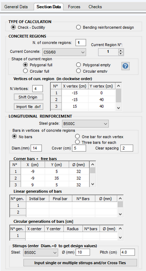
In the below Section Data window we select or assign:
- The option "Check" to perform bending check and a Shear check fixing generic diameter and pitch of the stirrups as desired (which can be subsequently modified in the absence of verification).
- N. of concrete region = 1 for the simple section at study which has a shape "Polygonal full"
- Coordinates of the four vertices of the concrete section with manual input (for complex sections you can import geometry and bars from a dxf file)
- As the different covers we are forced to select "No bars" option and manually enter the coordinates of the centroid of the four bars
- Materials classes for concrete and steel bars (for longitudinal and stirrups reinforcement)

In the Force window we assign the design forces described above for axial, biaxial bending and bending shear.
To compare the biaxial results with uniaxial ones we assign two additional combination (see below window) with separate uniaxial bending moment and shear forces (leaving unchanged the axia force).

RESULTS
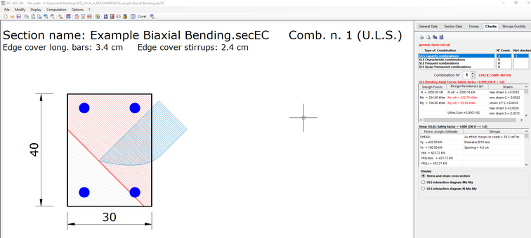
The numerical output results for biaxial bending (below reported) show a very slight difference the original example forces and the resulting resistances calculated by the program:
MxEd = 234 kNm; MxRd = 233.79 kNm
MyEd = 100 kNm; MxRd = 99.90 kNm
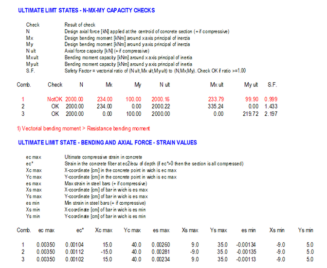
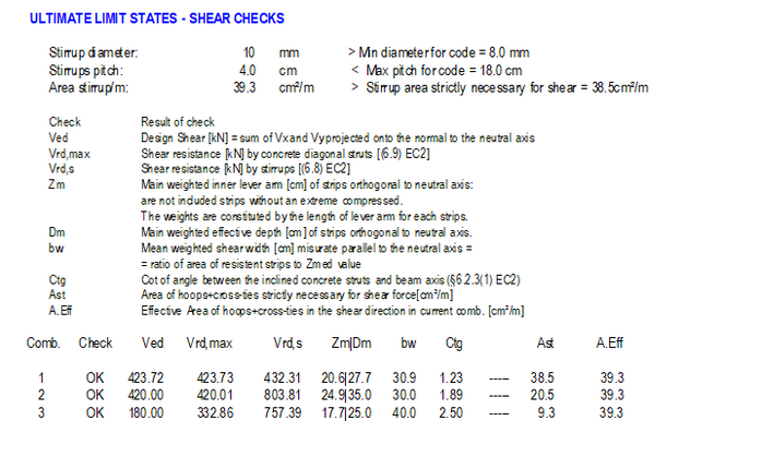
The numerical output for shear reinforcement (below reported) show that for the biaxial design shear forces is strictly necessary a two-leg hoop Φ10 / 4cm i.e. Asw = 38.5 cm²/m.while for separate uniaxial shear checks are strictly necessary Asw = 20.5 cm²/m for shear in y direction and Asw = 9.3 cm²/m for shear in x direction. This huge difference demonstrates the inadequacy of the calculation of the double uniaxial shear instead of the biaxial one.
