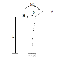
It is an approximate method which can be applied to an isostatic column (or which can be traced back to it) of the type shown in the figure. This column must also have the following characteristics:
- The cross section along the entire length must be rectangular and constant in both geometry and quantity and location of the reinforcements.
- The normal force N must be constant along the axis of the column.
- The hypothesis of a sinusoidal deformation is valid for which the maximum deflection δ at the top is a linear function of the curvature 1/r of the interlocking section:
![]()
The moment of the second order in the base section having maximum curvature equal to 1/r can, therefore, be written (setting p² = 10):
MII =N ⋅ δ = 0,4 N ⋅ L2 (1/r) (1)
Indicating with MI the bending moment of the first order, the total moment at the base of the cantilever can be written:
M = MI + MII (2)
The equilibrium condition of the interlocking section requires that the external moment provided by (2) be balanced by the internal one, whose trend is given by the moment-curvature diagram, to be determined at constant normal stress equal to N (normal design stress ).
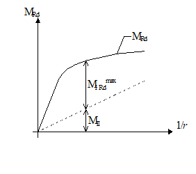
Reporting in this diagram M - 1/r, represented in Fig.2, the straight line (2) representing the moment of the second order, it is immediate to identify the maximum moment of the first order MI Rdmax available for the absorption of the calculation stress. It must be located in correspondence with the curvature in which the difference between the ordinate MRd of the resisting moment and that of the straight line MII (second order moment) reaches its maximum value.
The first order moment MI, referred to the critical cross section on the basis of the most unfavorable short-term actions H, M0, N, is given by:
MI = M0 + H L + N eni
where:
eni = l0 / 300 = unintentional eccentricity of the axial force to be assumed in any case to an extent of not less than 2 cm and 0.05 times the height h of the section
(l0 = length of free buckling).