The SPW software allows for analyses using the limit equilibrium method (L.E.M) and the finite element method (F.E.M). The first method can generally be used to perform a simplified calculation, thereby creating a preliminary design of the retaining wall and defining its main characteristics (embedment depth, diameter, etc.). This calculation only considers the static aspect of the problem, neglecting the actual deformability of the soil. Thus, the calculation is independent of the deformation state of the soil-structure complex. In contrast, by using the F.E.M., it is possible to perform both linear and nonlinear analyses, taking into account both the static and kinematic aspects. Therefore, the actual soil-structure interaction is considered, resulting in a more accurate calculation that aligns with the real behavior of the works.
Analysis with the Finite Element Method (F.E.M.)
The finite element method, as highlighted earlier, allows for more realistic analyses by considering the actual interaction between soil and structure. In this approach, the retaining wall is modeled as a set of beams with continuity constraints (beam elements) connected to the soil through elastic springs, whose stiffness is evaluated based on the elastic properties of the soil (Figure 1).
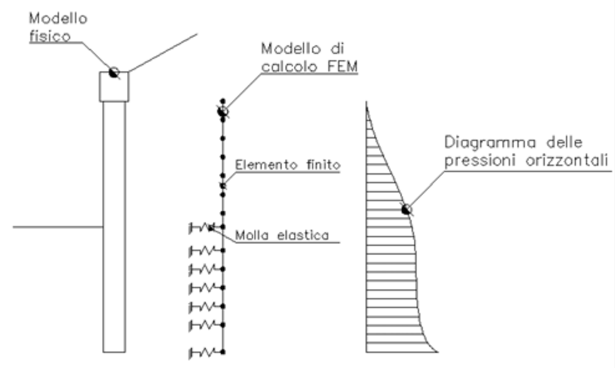
Figure 1: Schematic of a retaining wall using the finite element method
The stiffness calculation of the elastic springs (ks) is defined as the ratio between the ultimate resistance of the soil and the horizontal displacement:
![]()
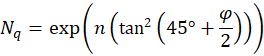
Such a relationship can be derived from pile load tests, or alternatively, it can be estimated based on formulations used for bearing capacity calculation using the following equation:
![]()
in where:
![]()
![]()
Z = depth considered
C = 40 obtained from the ratio ![]() by imposing a displacement
by imposing a displacement ![]() of 0.0254 m
of 0.0254 m
![]()
![]()
![]()
Therefore, once the stiffness modulus value of the spring ks, is determined, the software applies a force F at each node of the model calculated using the following relationship:
![]()
The calculation using this model, as demonstrated by Bowles (1974), can be considered in the calculation of the stresses induced in the region of the retaining wall subjected to passive pressure conditions. The model has been tested on numerous cases reported by Tschebotarioff (1949) and Rowe (1952), yielding satisfactory results.
To summarize, a linear analysis is initially performed where the displacements of the excavation base nodes are checked. If these displacements exceed the specified limit (0.0254) used in the calculation of ks, then a nonlinear analysis is initiated. This approach ensures that the ultimate limit states (ULS) of soil resistance are upheld..
Note (provided by the user on the transition from linear to nonlinear analysis)
© GeoStru