3 GROUND CONDITIONS AND SEISMIC ACTION (EC8 - part 1)
3.1 Ground conditions
3.1.2 Identification of ground types
1. Ground types A, B, C, D, and E, described by the stratigraphic profiles and parameters given in Table 3.1 and described hereafter, may be used to account for the influence of local ground conditions on the seismic action. This may also be done by additionally taking into account the influence of deep geology on the seismic action.
Note: The ground classification scheme accounting for deep geology for use in a country may be specified in its National Annex, including the values of the parameters S, TB, TC and TD defining the horizontal and vertical elastic response spectra in accordance with 3.2.2.2 and 3.2.2.3.
Ground type |
Description of stratigraphic profile |
Vs30 (m/s) |
NSPT (blows/30 cm) |
cu (kPa) |
|---|---|---|---|---|
A |
Rock or other rock-like geological formation, including at most 5 m of weaker material at the surface. |
>800 |
|
|
B |
Deposits of very dense sand, gravel, or very stiff clay, at least several tens of meters in thickness, characterized by a gradual increase of mechanical properties with depth. |
360-800 |
>50 |
>250 |
C |
Deep deposits of dense or medium-dense sand, gravel or stiff clay with thickness from several tens to many hundreds of meters. |
180-360 |
15-50 |
70-250 |
D |
Deposits of loose-to-medium cohesionless soil (with or without some soft cohesive layers), or of predominantly soft-to-firm cohesive soil. |
<180 |
<15 |
<70 |
E |
A soil profile consisting of a surface alluvium layer with v s values of type C or D and thickness varying between about 5 m and 20 m, underlain by stiffer material with v s > 800 m/s. |
|
|
|
S1 |
Deposits consisting, or containing a layer at least 10 m thick, of soft clays/silts with a high plasticity index (PI > 40) and high water content |
<100 (indicative) |
|
10-20 |
S2 |
Deposits of liquefiable soils, of sensitive clays, or any other soil profile not included in types A – E or S 1 |
|
|
|
Prospect 3.1-Ground types
2. The site should be classified according to the value of the average shear wave velocity, vs,30 , if this is available. Otherwise the value of NSPT should be used.
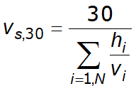
3. The average shear wave velocity vs,30 should be computed in accordance with the following expression:
|
(3.1) |
where hi and vi denote the thickness (in meters) and shear-wave velocity (at a shear strain level of 10–5 or less) of the i-th formation or layer, in a total of N, existing in the top 30 m.
4. For sites with ground conditions matching either one of the two special ground types S1 or S2 , special studies for the definition of the seismic action are required. For these types, and particularly for S2 , the possibility of soil failure under the seismic action shall be taken into account.
Note: Special attention should be paid if the deposit is of ground type S1 . Such soils typically have very low values of vs , low internal damping and an abnormally extended range of linear behaviour and can therefore produce anomalous seismic site amplification and soil-structure interaction effects (see EN 1998-5:2004, Section 6). In this case, a special study to define the seismic action should be carried out, in order to establish the dependence of the response
spectrum on the thickness and vs value of the soft clay/silt layer and on the stiffness contrast between this layer and the underlying materials.
3.2 Seismic action
3.2.1 Seismic zones
1. For the purpose of EN 1998, national territories shall be subdivided by the National Authorities into seismic zones, depending on the local hazard. By definition, the hazard within each zone is assumed to be constant.
2. For most of the applications of EN 1998, the hazard is described in terms of a single parameter, i.e. the value of the reference peak ground acceleration on type A ground, agR . Additional parameters required for specific types of structures are given in the relevant Parts of EN 1998.
Note: The reference peak ground acceleration on type A ground, agR , for use in a country or parts of the country, may be derived from zonation maps found in its National Annex.
3. The reference peak ground acceleration, chosen by the National Authorities for each seismic zone, corresponds to the reference return period TNCR of the seismic action for the no-collapse requirement (or equivalently the reference probability of exceedance in 50 years, PNCR ) chosen by the National Authorities (see 2.1(1)P). An importance factor γI equal to 1,0 is assigned to this reference return period. For return periods other than the reference (see importance classes in 2.1(3)P and (4)), the design ground acceleration on type A ground ag is equal toagR times the importance factor γI (ag =gI x agR ). (See Note to 2.1(4)).
4. In cases of low seismicity, reduced or simplified seismic design procedures for certain types or categories of structures may be used.
Note: The selection of the categories of structures, ground types and seismic zones in a country for which the provisions of low seismicity apply may be found in its National Annex. It is recommended to consider as low seismicity cases either those in which the design ground acceleration on type A ground, ag , is not greater than 0,08g (0,78 m/s2), or those where the product ag x S is not greater than 0,1 g (0,98 m/s2). The selection of whether the value of ag , or that of the product ag x S will be used in a country to define the threshold for low seismicity cases, may be found in its National Annex.
5. In cases of very low seismicity, the provisions of EN 1998 need not be observed.
Note: The selection of the categories of structures, ground types and seismic zones in a country for which the EN 1998 provisions need not be observed (cases of very low seismicity) may be found in its National Annex. It is recommended to consider as very low seismicity cases either those in which the design ground acceleration on type A ground, ag , is not greater than 0,04g (0,39 m/s2), or those where the product ag x S is not greater than 0,05g (0,49 m/s2). The selection of whether the value of ag , or that of the product ag x S will be used in a country to define the threshold for very low seismicity cases, can be found in its National Annex.
3.2.2 Basic representation of the seismic action
3.2.2.1 General
1. Within the scope of EN 1998 the earthquake motion at a given point on the surface is represented by an elastic ground acceleration response spectrum, henceforth called an “elastic response spectrum”.
2. The shape of the elastic response spectrum is taken as being the same for the two levels of seismic action introduced in 2.1(1)P and 2.2.1(1)P for the no-collapse requirement (ultimate limit state – design seismic action) and for the damage limitation requirement.
3. The horizontal seismic action is described by two orthogonal components assumed as being independent and represented by the same response spectrum.
4. For the three components of the seismic action, one or more alternative shapes of response spectra may be adopted, depending on the seismic sources and the earthquake magnitudes generated from them.
3.2.2.2 Horizontal elastic response spectrum
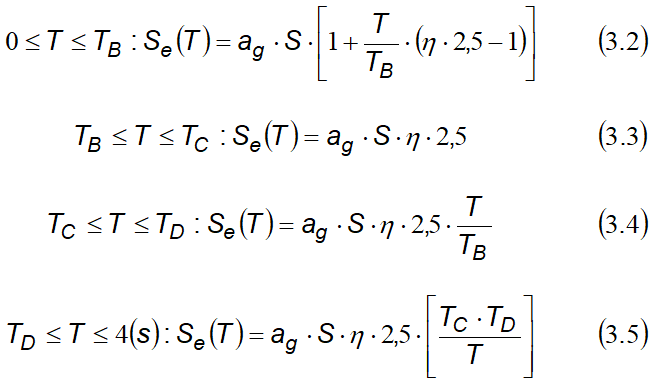
1. For the horizontal components of the seismic action, the elastic response spectrum Se(T) is defined by the following expressions (see Figure. 3.1):
where:
Se(T ) is the elastic response spectrum;
T is the vibration period of a linear single-degree-of-freedom system;
ag is the design ground acceleration on type A ground (ag =γIagR);
TB is the lower limit of the period of the constant spectral acceleration branch;
TC is the upper limit of the period of the constant spectral acceleration branch;
TD is the value defining the beginning of the constant displacement response range of the spectrum;
S is the soil factor;
η is the damping correction factor with a reference value of η= 1for 5% viscous damping, see (3) of this subclause.
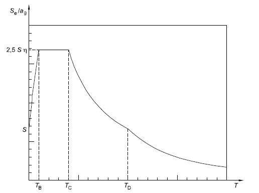
Figure 3.1 - Shape of the elastic response spectrum
2. The values of the periods TB , TC and TD and of the soil factor S describing the shape of the elastic response spectrum depend upon the ground type.
Note 1: The values to be ascribed to TB , TC , TD and S for each ground type and type (shape) of spectrum to be used in a country may be found in its National Annex. If deep geology is not accounted for (see 3.1.2(1) ), the recommended choice is the use of two types of spectra: Type 1 and Type 2. If the earthquakes that contribute most to the seismic hazard defined for the site for the purpose of probabilistic hazard assessment have a surface-wave magnitude, Ms , not greater than 5,5, it is recommended that the Type 2 spectrum is adopted. For the five ground types A, B, C, D and E the recommended values of the parameters S, TB , TC and TD are given in Table 3.2 for the Type 1 Spectrum and in Table 3.3 for the Type 2 Spectrum. Figure 3.2 and Figure 3.3 show
the shapes of the recommended Type 1 and Type 2 spectra, respectively, normalized by a g, for 5% damping. Different spectra may be defined in the National Annex, if deep geology is accounted for.
Ground type |
S |
TB(s) |
TC(s) |
TD(s) |
|---|---|---|---|---|
A |
1,0 |
0,15 |
0,4 |
2,0 |
B |
1,2 |
0,15 |
0,5 |
2,0 |
C |
1,15 |
0,20 |
0,6 |
2,0 |
D |
1,35 |
0,20 |
0,8 |
2,0 |
E |
1,4 |
0,15 |
0,15 |
2,0 |
Table 3.2 - Values of the parameters describing the recommended Type 1 elastic response spectra
Ground type |
S |
TB(s) |
TC(s) |
TD(s) |
|---|---|---|---|---|
A |
1,0 |
0,05 |
0,25 |
1,2 |
B |
1,35 |
0,05 |
0,25 |
1,2 |
C |
1,5 |
0,10 |
0,25 |
1,2 |
D |
1,8 |
0,10 |
0,30 |
1,2 |
E |
1,6 |
0,05 |
0,25 |
1,2 |
Table 3.3 - Values of the parameters describing the recommended Type 2 elastic response spectra
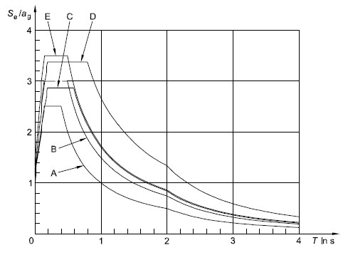
Figure 3.2 - Recommended Type 1 elastic response spectra for ground types A to E (5% damping)
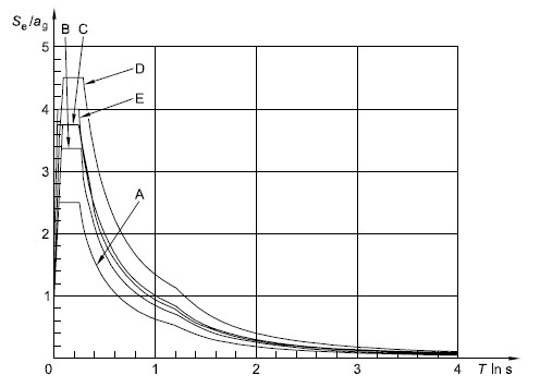
Figure 3.3 - Recommended Type 2 elastic response spectra for ground types A to E (5% damping)
Note 2: For ground types S1 and S2, special studies should provide the corresponding values of S, TB , TC and TD.
3. The value of the damping correction factor ηmay be determined by the expression:
|
(3.6) |
where:
x is the viscous damping ratio of the structure, expressed as a percentage.
4. If for special cases a viscous damping ratio different from 5% is to be used, this value is given in the relevant Part of EN 1998.
5. The elastic displacement response spectrum, SDe(T), shall be obtained by direct transformation of the elastic acceleration response spectrum, Se(T), using the following expression:
|
(3.7) |
6. Expression (3.7) should normally be applied for vibration periods not exceeding 4,0 s. For structures with vibration periods longer than 4,0 s, a more complete definition of the elastic displacement spectrum is possible.
Note: For the Type 1 elastic response spectrum referred to in Note 1 to 3.2.2.2(2)P, such a definition is presented in Informative Annex A in terms of the displacement response spectrum. For periods longer than 4,0 s, the elastic acceleration response spectrum may be derived from the elastic displacement response spectrum by inverting expression (3.7).
3.2.2.3 Vertical elastic response spectrum
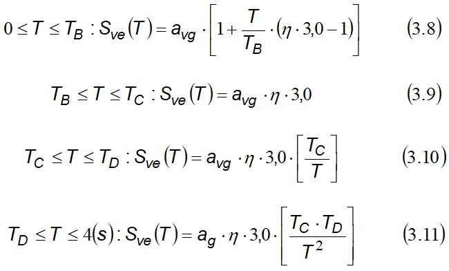
1. The vertical component of the seismic action shall be represented by an elastic response spectrum, Sve(T), derived using expressions (3.8)-(3.11).
Note: The values to be ascribed to TB , TC , TD and avg for each type (shape) of vertical spectrum to be used in a country may be found in its National Annex. The recommended choice is the use of two types of vertical spectra: Type 1 and Type 2. As for the spectra defining the horizontal components of the seismic action, if the earthquakes that contribute most to the seismic hazard defined for the site for the purpose of probabilistic hazard assessment have a surface-wave magnitude, Ms , not greater than 5,5, it is recommended that the Type 2 spectrum is adopted. For the five ground types A, B, C, D and E the recommended values of the parameters describing the vertical spectra are given in Table 3.4. These recommended values do not apply for special ground types S1 and S2 .
Spectrum |
avg/ag |
TB(s) |
TC(s) |
TD(s) |
|---|---|---|---|---|
Type 1 |
0,90 |
0,05 |
0,15 |
1,0 |
Type 2 |
0,45 |
0,05 |
0,15 |
1,0 |
Table 3.4 - Recommended values of parameters describing the vertical elastic response spectra
2. To avoid explicit inelastic structural analysis in design, the capacity of the structure to dissipate energy, through mainly ductile behaviour of its elements and/or other mechanisms, is taken into account by performing an elastic analysis based on a response spectrum reduced with respect to the elastic one, henceforth called a ''design spectrum''. This reduction is accomplished by introducing the behaviour factor q.
3.The behaviour factor q is an approximation of the ratio of the seismic forces that the structure would experience if its response was completely elastic with 5% viscous damping, to the seismic forces that may be used in the design, with a conventional elastic analysis model, still ensuring a satisfactory response of the structure. The values of the behaviour factor q, which also account for the influence of the viscous damping being different from 5%, are given for various materials and structural systems according to the relevant ductility classes in the various Parts of EN 1998. The value of the behaviour factor q may be different in different horizontal directions of the structure, although the ductility classification shall be the same in all directions.
4.For the horizontal components of the seismic action the design spectrum, Sd(T), shall be defined by the following expressions:
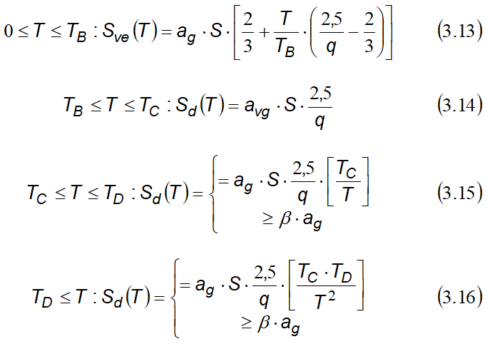
where:
ag, S, TC e TD are as defined in 3.2.2.2;
Sd(T ) is the design spectrum;
q is the behaviour factor;
β is the lower bound factor for the horizontal design spectrum.
Note: The value to be ascribed to ß for use in a country can be found in its National Annex. The recommended value for β is 0,2.
5.For the vertical component of the seismic action the design spectrum is given by expressions (3.13) to (3.16), with the design ground acceleration in the vertical direction, avg replacing ag , S taken as being equal to 1,0 and the other parameters as defined in 3.2.2.3.
6.For the vertical component of the seismic action a behaviour factor q up to to 1,5 should generally be adopted for all materials and structural systems.
7.The adoption of values for q greater than 1,5 in the vertical direction should be justified through an appropriate analysis.
8.The design spectrum as defined above is not sufficient for the design of structures with base-isolation or energy-dissipation systems.
3.2.3 Alternative representations of the seismic action
3.2.3.1 Time - history representation
3.2.3.1.1 General
1.The seismic motion may also be represented in terms of ground acceleration time-histories and related quantities (velocity and displacement)
2.When a spatial model is required, the seismic motion shall consist of three simultaneously acting accelerograms. The same accelerogram may not be used simultaneously along both horizontal directions. Simplifications are possible in accordance with the relevant Parts of EN 1998.
3.Depending on the nature of the application and on the information actually available, the description of the seismic motion may be made by using artificial accelerograms (see 3.2.3.1.2) and recorded or simulated accelerograms (see 3.2.3.1.3).
3.2.3.1.2 Artificial accelerograms
1. Artificial accelerograms shall be generated so as to match the elastic response spectra given in 3.2.2.2 and 3.2.2.3 for 5% viscous damping (ξ= 5%).
2.The duration of the accelerograms shall be consistent with the magnitude and the other relevant features of the seismic event underlying the establishment of ag .
3. When site-specific data are not available, the minimum duration T s of the stationary part of the accelerograms should be equal to 10 s.
4. The suite of artificial accelerograms should observe the following rules:
a) a minimum of 3 accelerograms should be used;
b) the mean of the zero period spectral response acceleration values (calculated from the individual time histories) should not be smaller than the value of agS for the site in question.
c) in the range of periods between 0,2T1 and 2T1 , where T1 is the fundamental period of the structure in the direction where the accelerogram will be applied; no value of the mean 5% damping elastic spectrum, calculated from all time histories, should be less than 90% of the corresponding value of the 5% damping elastic response spectrum.
3.2.3.1.3 Recorded or simulated accelerograms
1. Recorded accelerograms, or accelerograms generated through a physical simulation of source and travel path mechanisms, may be used, provided that the samples used are adequately qualified with regard to the seismogenetic features of the sources and to the soil conditions appropriate to the site, and their values are scaled to the value of a agS for the zone under consideration.
2. For soil amplification analyses and for dynamic slope stability verifications see EN 1998-5:2004, 2.2.
3. The suite of recorded or simulated accelerograms to be used should satisfy 3.2.3.1.2(4).
3.2.3.2 Spatial model of the seismic action
1. For structures with special characteristics such that the assumption of the same excitation at all support points cannot reasonably be made, spatial models of the seismic action shall be used (see 3.2.2.1(8)).
2.Such spatial models shall be consistent with the elastic response spectra used for the basic definition of the seismic action in accordance with 3.2.2.2 and 3.2.2.3.
3.2.4 Combinations of the seismic action with other actions
1.The design value Ed of the effects of actions in the seismic design situation shall be determined in accordance with EN 1990:2002, 6.4.3.4.
2.The inertial effects of the design seismic action shall be evaluated by taking into account the presence of the masses associated with all gravity loads appearing in the following combination of actions:
|
(3.17) |
where:
ΨE,i is the combination coefficient for variable action i (see 4.2.4).
3.The combination coefficients ΨE,i take into account the likelihood of the loads Qk,i not being present over the entire structure during the earthquake. These coefficients may also account for a reduced participation of masses in the motion of the structure due to the non-rigid connection between them.
4.Values of Ψ2,i are given in EN 1990:2002 and values of ΨE,i other types of structures are given in the relevant parts of EN 1998
4.1.3 Slope stability
4.1.3.3 Methods of analysis (EC 8-part 5)
1.The response of ground slopes to the design earthquake shall be calculated either by means of established methods of dynamic analysis, such as finite elements or rigid block models, or by simplified pseudo-static methods subject to the limitations of (3) and (8) of this subclause.
2.In modelling the mechanical behaviour of the soil media, the softening of the response with increasing strain level, and the possible effects of pore pressure increase under cyclic loading shall be taken into account.
3.The stability verification may be carried out by means of simplified pseudostatic methods where the surface topography and soil stratigraphy do not present very abrupt irregularities.
4.The pseudo-static methods of stability analysis are similar to those indicated in EN 1997-1:2004, 11.5, except for the inclusion of horizontal and vertical inertia forces applied to every portion of the soil mass and to any gravity loads acting on top of the slope.
5.The design seismic inertia forces FH and FV acting on the ground mass, for the horizontal and vertical directions respectively, in pseudo-static analyses shall be taken as:
FH = 0,5 a S W
FV = ± 0,5 FH if the ratio avg/ag is greater than 0,6
FV = ± 0,33 FH if the ratio avg/ag is not greater than 0,6.
Where:
a is the ratio of the design ground acceleration on type A ground, ag , to the acceleration of gravity g;
avg is the design ground acceleration in the vertical direction;
ag is the design ground acceleration for type A ground;
S is the soil parameter of EN 1998-1:2004, 3.2.2.2;
W is the weight of the sliding mass.
A topographic amplification factor for a g shall be taken into account according to 4.1.3.2 (2).
6. A limit state condition shall then be checked for the least safe potential slip surface.
7. The serviceability limit state condition may be checked by calculating the permanent displacement of the sliding mass by using a simplified dynamic model consisting of a rigid block sliding against a friction force on the slope. In this model the seismic action should be a time history representation in accordance with 2.2 and based on the design acceleration without reductions.
8. Simplified methods, such as the pseudo-static simplified methods mentioned in (3) to (6) in this subclause, shall not be used for soils capable of developing high pore water pressures or significant degradation of stiffness under cyclic loading.
9. The pore pressure increment should be evaluated using appropriate tests. In the absence of such tests, and for the purpose of preliminary design, it may be estimated through empirical correlations.
© GeoStru
