The limit equilibrium method consists in looking for solutions that are compatible only with the static aspect of the problem. Basically, we reason in terms of equilibrium of a rigid body, without minding the kinematic congruence of the displacements. The main calculation diagrams we will refer to are the following:
•Overhanging bulkhead
•Anchored bulkhead with free end
•Anchored bulkhead with fixed end
Overhanging bulkhead
Calculation of the limit embedment depth
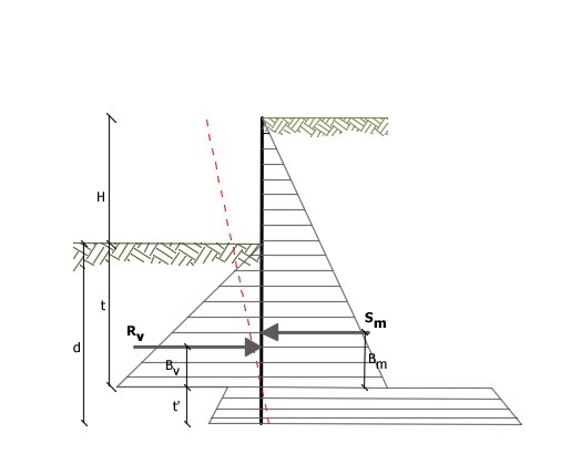
For unanchored bulkhead, the stability is guaranteed by the passive strength of the ground situated downhill from it; from the equilibrium of the moments as to the center of rotation, we obtain:
![]()
Where the symbols have the following meaning:
Sm = horizontal component of the active thrust
Bm = arm of Sm as to O center of rotation
Rv = horizontal component of the passive strength
Bv = arm of Rv as to O center of rotation
Each term is a function of t, where t is the depth of the rotation center with respect to the downhill reference level (downhill natural surface level). The necessary length to guarantee the equilibrium of the horizontal translation is obtained by increasing t as follows:
![]()
where a=0.2 (Blum method)
Reference diagram for calculating the equilibrium of the bulkhead
Safety factor on the passive strength
The length of the embedment d, as determined above, refers to the limit condition of an incipient collapse through a coefficient F. It is possible to introduce a safety margin on the passive strengths; such reduction is made as follows:
![]()
Anchored bulkhead with free end
Calculation of the limit embedment depth
The stability of the work is also guaranteed by the anchors fastened upon the bulkhead. In order to use the calculation scheme with free end, the bulkhead must be sufficiently short and rigid. The embedment length will be determined by imposing the equilibrium to the rotation on the origin of the anchor indicated as B1
![]()
Where the symbols have following meaning:
Sm = horizontal component of the active thrust
H = height of the ground to be supported
t = calculated embedment depth
Bm = arm of Sm as to the base of the bulkhead
Pm = ordinate of the point of application of the upstream anchor
Rv = horizontal component of the passive strength
Bv = arm of Rv
When t is known, Sm and Rv as well as the stress of the anchor will be determined.
Safety factor F on the passive strengths
The embedment length will be further increased so as to have a safety margin in working conditions by means of the safety factor F:
![]()
Anchored bulkhead with fixed end
Calculation of the limit embedment depth
If the deepest section of the bulkhead does not translate or rotate, it can be assimilated to a fixed joint; in this case, the bulkhead is defined with fixed end. A procedure developed by BLUM allows obtaining the embedment depth (t+t'), imposing the kinematic conditions of null displacements on the base of the work and on the origin of the anchor (B1) and the static conditions of null moment and shear on the base of the bulkhead. We therefore reach a 5th degree equation in (t+t') which can be easily solved.
Safety factor F on the strengths
In order to increase the safety factor, values of the reduced passive strengths have been introduced in the numerical developments.
© GeoStru