The calculation of the ultimate moment resistance MRd of rc cross-section is based on the following assumptions (§6.1 EC2):
•plane sections remain plane
•the strain in bonded reinforcement is the same as that in the surrounding concrete
•tensile stresses of concrete are ignored (no strength in tension)
•the stresses in the concrete in compression are derived from the design stress-strain relationship illustrated in the following
•the stresses in the reinforcing steel are derived from the design curves showed in the following
Stress-strain relation for the design of concrete
For the design of cross-sections program uses the parabola-rectangle stress-strain relationship according to §3.1.7 EC2 depicted in the follow figure.
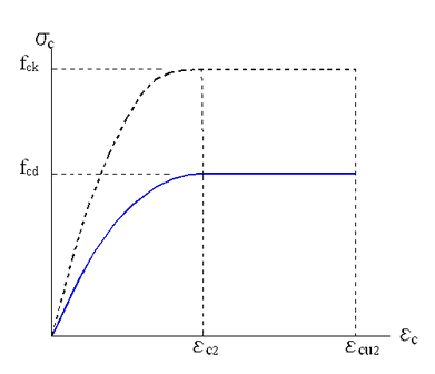
The value of the design compressive strength fcd is:
fcd = αcc fck /γc (3.15)EC2
where:
γc = 1.5 is the partial safety factor for concrete
αcc is a coefficient taking account of long term effect... (recommended value = 1.0 but editable in Code and reinforcement options)
The parabola-rectangle in figure is described by the following function:
σc = fcd [ 1- ( 1 - εc / εc2 )n ] for 0≤ εc≤ εc2 (3.17)EC2
σc = fcd for εc2≤ εc≤ εcu2 (3.17)EC2
εc2 = is the strain at reaching the maximum strength = 0.0020 for fck ≤ 50 Mpa
= 0.0020 + 0.000085(fck-50)0.53 for fck ≥ 50 Mpa
εcu2 = is the ultimate strength = 0.0035 for fck ≤ 50 Mpa
= 0.0026 + 0.00035[(90-fck)/100]0.53 for fck ≥ 50 Mpa
n = 2.0 for fck ≤ 50 Mpa
= 1.4+23.4[(90-fck)/100]4 for fck ≥ 50 Mpa
Stress-strain relation for the design of steel
For the design of cross-sections program uses one the bilinear stress-strain relationships according to §3.2.7 EC2 depicted in the follow figure.
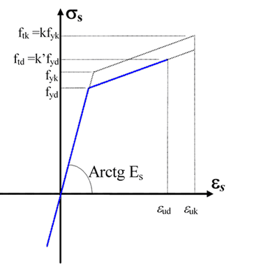
The inclined top branch has a strain design limit εud= ku · εuk a yield stress fyd = fyk/γs and a maximum stress fyd max = k fyk/γs
where:
εuk = ultimate characteristic strain (ductility)
ku = reduction factor for εuk (= 0.9 recommended in EC2; but you can edit a different value according to National Annex in Code and Reinforcement options)
k = fyk/fyk this ratio can vary from 0 to 1.35
In §3.2.7(2) EC2 is allowed to set k=1.0 (horizontal top branch without strain limit) independently of the actual value of fyk/fyk .
The actual min or/and max value of fyk/fyk vary according to the class of steel (i.e. for class C the ratio 1.15 ≤fyk/fyk ≤ 1.35) (see Annex C EC2)
In the program you can set (in the Materials Library) any k ≥ 1.0 for design checks independently of the actual value of fyk/fyk (but pay attention to respect the min and max actual value of fyk/fyk )
In the program you can set freely (in the Materials Library) the value εuk but you must pay attention to respect the actual ultimate strain (see Annex C EC2)
|
© 2020 Geostru