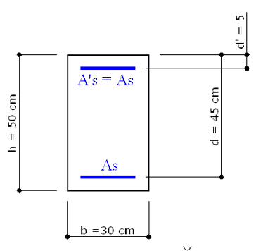
The above cross section of a column refers to Example 5.3 in /6/. C30/37 is the concrete class and S500C is the steel grade.
The concrete design strength is: fcd = αcc⋅ fck / γc = 0.85 ⋅ 30 / 1.5 = 17.0 Mpa
The steel design yield strength is: fyd = fyk/ γs = 450/1.15 = 391.3 Mpa
The problem is to design the longitudinal reinforcement distributed over only two level of the same areas As under the assigned ULS forces: N=1875 kN; Mx=280 kN.
In addition to the above question we want to design shear reinforcement for a ULS shear design force VEd = 300 kN.
INPUT DATA
Once opened a new calculation (by means the command "New" in the menu File) it is important to control if the default Code setting options agree with those in the given example to compare.
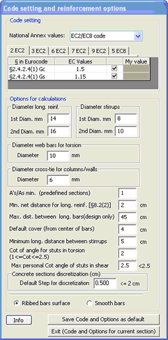
In this example we control, in particular, the parameters γc, γs , αcc. The EC2 recommended value of the last parameter αcc is 1.00 and it is to change in 0.85 as in the example. If a specific National Annex is selected no change is necessary. In the design context of this example it is important to set the following reinforcement options:
- Diameter of longitudinal reinforcement (below set at 14 and 16 mm) but for predefined section the diameter is an input parameter in design context
- Diameter of stirrups (below set to 8 and 10 mm)
- A'/A below set to 1 because the member of the section is a column
- Min net distance between longitudinal bars set to 2 (this distance must be assigned in according to § 8.2 EC2 and with the diameters just assigned)
- Max distance between longitudinal bar set to 45 cm to avoid the design of bars at intermediate level not provided in the assumed example
- Max personal max value of cot θ = 2.5 as usual in reinforcement shear design
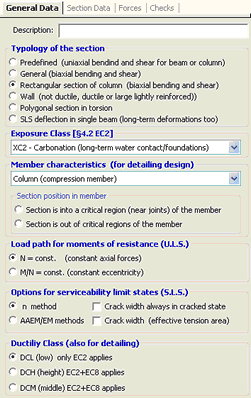
In the below "General Data" windows we selected the typology "Rectangular section of column" suited for the present example; the other data are the same of the previous example.
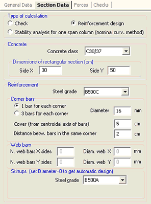
In the below Section Data window we select:
- The option "Reinforcement Design" to perform, at the same time, bending and shear design or reinforcement (when you reopen this window the selection is at check option so you must reselect the design option to run in this modality)
- Materials classes for concrete and steel bars (for longitudinal and stirrups reinforcement)
- Dimension of rectangular section
- Type of arrangement of corner bars (one bar for each corner) and bar diameter
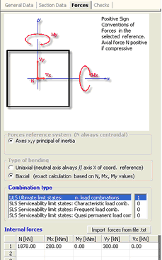
In the above Forces window we assigned, as ULS combinations, the axial and uniaxial bending forces of assumed Example 5.3 in /6/. For the shear design we added the uniaxial shear force Vx = VEd = 300 kN.
RESULTS
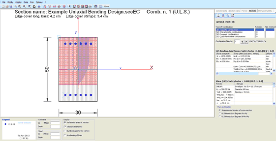
The total area of designed bars (6+6 Φ 16) is 24.13 cm² (as you may see in the legend box). This area is very near to that (23.45 cm²) of the assumed example calculated by means of an abacus.
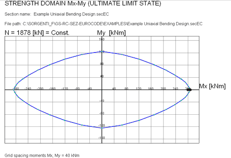
The bending resistance (287.2 kNm) is slightly greater than the design value (280.0) as you may graphical control in the below interaction diagram (black circle is the design value and the red one is the reistance).
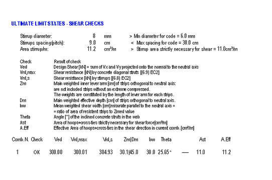
The shear design performed by the program has produced the following two legs stirrups: Φ 8 / 9 cm. The check results are: