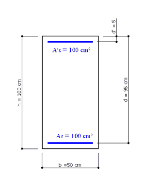
The above cross section of a column refers to Example 6.1 in /4/. C30/37 is the concrete class and S450C is the steel grade.
The concrete design strength is: fcd = αcc⋅ fck / γc = 0.85 ⋅ 30 / 1.5 = 17.0 Mpa
The steel design yield strength is: fyd = fyk/ γs = 450/1.15 = 391.3 Mpa
The problem is to assess uniaxial moments of resistance under the following axial loads: 600 kN; 2000 kN; 5000 kN; 10000 kN.
We want check the same section with the program and compare the results.
INPUT DATA
Once opened a new calculation (by means the command "New" in the menu File) it is important to control if the default Code setting options agree with those in the given example to compare.
In this example we control, in particular, the parameters γc, γs , αcc. The EC2 recommended value of the last parameter αcc is 1.00 and it is to change in 0.85 as in the example. If a specific National Annex is selected no change is necessary.
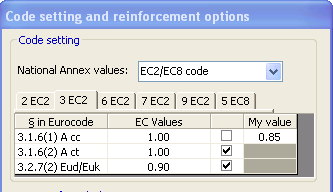
The others default code parameters are the same.
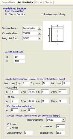
The filled General Data and the pertinent Section Data windows are:
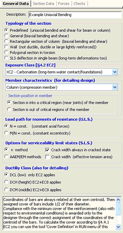
In the above General Data window we have selected the "Predefined" typology and "Columns" as member characteristics. We left unchanged the default value of Load path (N=cost.) so to calculate bending capacities with assigned values of N taken as constants. The section belongs to a structure not in seismic zone then low ductility class DCL applies (only EC2 rules).
In the Section Data window we left the default type of calculation (Check) and typology (Predefined section for uniaxial forces check). In the three combo boxes we selected the shape (rectangular) and the same classes of the materials provided in the example. After setting the actual sizes of the section (50x100) and the covers (5 cm), we simulated the areas of the two row of longitudinal reinforcement As = A's = 50 cm² as obtained by 6+6 bars all with the same fictitious diameter of 32.573 mm.
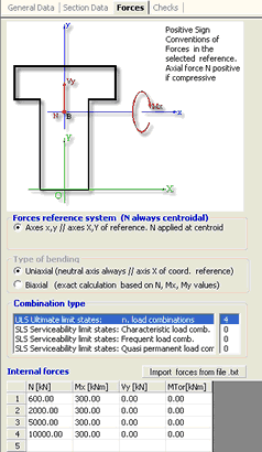
In the above Forces window we assigned, as ULS combinations, the above four axial forces and generic values (300 kNm) for the correspondent moments; this because we want to assess only the bending capacities without compare the actual moments.
RESULTS
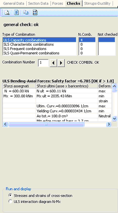
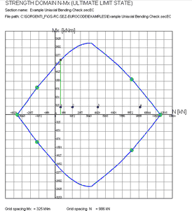
Selecting the Checks tab we obtained the below results window, printed results window (command on the local tab bar) and interaction diagram N-Mx (option in the lower part of this window):
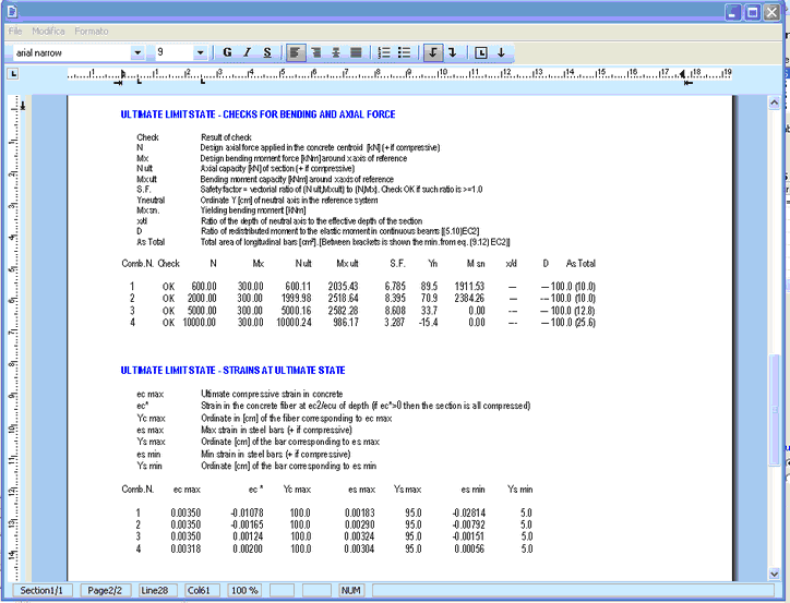
In the below table the values of ultimate moments MRd obtained in the aforementioned example are compared with the just reported results Mx ult. The differences are very small despite the different methods of calculation:
NEd (kN) |
MRd (kNm) |
Mx ult (kNm) |
600 |
2031 |
2035 |
2000 |
2524 |
2519 |
5000 |
2606 |
2582 |
10000 |
1000 |
986 |