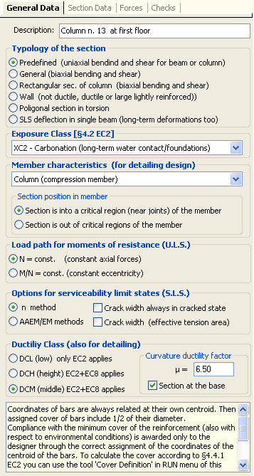
This is the first window to fill for a new project. These are the principal input data:
Typology of the section
The five choices provided are:
-Predefined sections: rectangular, T, rectangular with flanges, circular. Bending and shear forces are only uniaxial. Checks or design of reinforcement.
-General sectionsi: are formed by one or more concrete regions polygonal or circular shaped with reinforcement however arranged. The bending moment and shear forces can be selected as uniaxial or biaxial. In general it is expected to only checks calculation. For polygonal sections formed by a single concrete region can also be performed the design of longitudinal bars.
-Rectangular section of colums: the arrangement of the reinforcement is always doubly symmetrical. The calculation is always biaxial in bending and shear. Check or design of reinforcement.
-Rectangular section of walls: the arrangement of the reinforcement is always doubly symmetrical. Program performs only checks calculation in biaxial bending and uniaxial shear.
-Polygonal section torsion: simple torsion check for polygonal sections (hollow or not).
-SLS deflections in simple beam: the beam can be isolated or belongs to a frame.
Exposure class
This selection, according to § 4.2 EC2, affects the definition of the concrete to be used in the project of the section. The user is responsible for the consistent choice of the concrete class (program do not perform any compatibility check between exposure class and concrete class).
Member characteristics
Defines the type of member to which the section belongs: beam, column, beam, foundation beam in seismic zone, beam without stirrups. If the project is in seismic zone the user must indicate if the current section is located within or not a critical region according to the section 5 of EC8. The checks take in account the detailing rules according to §9 EC2 and §5 EC8.
Load path for moments of resistance
The calculation of the resistance moment force for a given design moment and axial force may be performed by program with a constant ratio M/N or keeping N= constant. The second way must be choose in seismic checks.
Options for serviceability limit states (SLS): user may choose between simplified method (n method) that assimilates rheological phenomena of the conglomerate placing equal to 15, the coefficient n of homogenization (n=Es/Ec is editable in the appropriate grid of the materials library), and il AAEM method that take in account the values assigned to creep, shrinkage and ageing in the concrete grid in the materials library. It should be noted that the assignment of the serviceability combination forces is optional unlike those of resistance that must always be assigned (at least one). In order to set always zero the tension strength in cracking zones of concrete for crack width calculations, you may select the appropriate check box. If you want to calculate the crack width setting e2 of (7.13)EC2 as the value at the edge of effective tension region of concrete you may select the appropriate check box.
Ductility Class
Low ductility class DCL includes all section to be calculated only with EC2 standards while Height (DCH) and Middle (DCM) Classes include all the section required by EC8 in seismic zones. For beams in DCH or DCM classes and within critical regions of the member you should assign the curvature ductility factor m in order to respect the eq. (5.11)EC8. Idem for columns in order to respect the eq. (5.15)EC8 when expected; alternatively for direct check of local ductility it is possible to generate the moment-curvature diagram selecting the Stirrups-Ductility Tab.
|
© 2020 Geostru