With reference to SLS combinations compressive stresses in the concrete shall be limited in order to avoid longitudinal cracks, micro-cracks and high level of creep. Stresses in the reinforcement shall be limited in order to avoid unacceptable cracking or deformations.
In the calculation of stresses cross sections are assumed by the program uncracked if concrete flexural tensile stress does not exceed fctm and if the option "Crack width always in cracked state" (see General Data window) is not checked. But if in at least one combination among those assigned, is exceeded the value of fctm, then all combinations are checked as cracked. If the above option is checked then cross section is assumed cracked for all SLS combinations without tensile control.
For characteristic combination forces program assumes as critical value of concrete compressive stress: k1 ⋅ fck (k1 = 0.60 is the recommended value; to modify k1 in according to national annex see Code and reinforcement options).
For characteristic combination forces program assumes as critical value of steel tension: k3 ⋅ fyk (k3 = 0.80 is the recommended value).
For quasi-permanent combination forces program assumes as critical value of concrete compressive stress: k2 ⋅ fck (k2 = 0.45 is the recommended value).
Program provides two calculation method for SLS stresses evaluation: Simplified method and AEEM (or EM) method.
Simplified method (n method)
The stress-strain relationship is always linear both for the concrete (for tension stress not exceeding fctm) that for the steel. Area of steel bar is amplified with the factor n = Es/Ec. In general the value assumed for n is 15 to take in account creep effects (long time effects) on stresses redistribution. Anyhow you can set n value for each concrete class in Materials Library window (for characteristic combinations only may be better not to take in account creep and set n = Esm/Ecm ).
Calculation procedure:
for the hypothesis of conservation of plane sections the deformation of the cross section may be expressed by means of a plane ε(x,y) the equation of which is:
ε(x,y) = a x + b y + c (1)
where a, b are the curvatures of the plane around x and y axes of refence assumed, and c is the strain at the origin of refence axes.
Now we express the neutral axis as the intersection of above plane (1) with the plane undeformed ε(x,y) = 0:
a x + b y + c = 0 (2)
The stresses in a generic point x,y of the concrete region j are:
σcj(x,y) = Ecj ε(x,y) = Ecj ( a x + b y +c ) if ε > 0
(3)
σcj(x,y) = 0 if ε ≤ 0
where Ecj is the elastic modulus of concrete region j.
similarly, for the generic steel bar which centre has coordinates xi, yi:
σs (xi, yi) = Es ( a xi + b yi + c ) (4)
indicating with Aj the effective area (which stress is greater then fctm) of region j and with Ai the area of the single bar i, the three equations of equilibrium are:
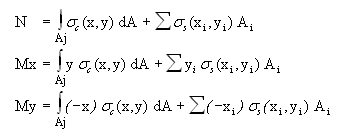
Areas, static moments and moments of the second order, can be written:
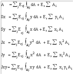
Substituting (3) into (5) and taking into account last relations, we obtain the following non-linear system in the unknowns a, b, c :
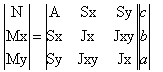 (5)
(5)
The iterative solution of the above system provides the coefficients a, b, c and then the stresses by means of the relationships (3) and (4).
AAEM method
AAEM (Age Adjusted Effective Modulus) provides a more refined evaluation of stresses and deformations of cross sections taking into account the assigned values (in Materials Library)of creep φ(t,t0), shrinkage ε(t,t0) and of the time of load application (for cracked and uncracked sections). EC2 standards not provide any guidance on this method of calculation, but merely provide the rheological data of the concrete (see Concrete rheological coefficients).
You can assume this method for SLS checks selecting the pertinent option in General data window. Program use as default this method in SLS deformation checks.
AAEM method is based on a double calculation of the same section:
•evaluation of instantaneous stresses at time t0 of first loading;
•evaluation of stresses changes due to creep and shrinkage from t0 to the final time t. Program assume the simplifying assumption that, after t0, bending and axial force remain constant up to time t (this is strictly true only for isostatic members).
For a compressed concrete sample not reinforced and without any constrains the creep coefficient f(t,t0) is defined at time t0 as:
f(t,t0) = s0 / e0 (6)
where e0 = s0 / Ec(t0) (7)
This theory is valid for s0 ≤ 0.45 fck(t0).
If from (6) we express the strain e0 in function of time we have:
e(t,t0) = s0 [1 + f(t,t0) ]
If after t0 of first stress s0 , we have a gradual reduction of stress ds, the superposition principle allows us to express the strain at time t, as follows (including shrinkageecs too):
e(t) = ecs(t,t0) + s0 [ 1 + f(t,t0) ] / Ec(t0) +Ec(τ) [1+f(t,τ)] ds (8)
To avoid the difficulties of integrations of differential relation (8) the method replaces the actual load history σ(t) with a single stress increase Δσ and a creep coefficient f(t,t0) reduced by means of the so-called coefficient of aging c = c(t,t0):
e(t) = s0 [1+f] / Ec(t0) + Δs(t) [1+c f] / Ec(t0) + ecs (9)
where ecs = ecs(t,t0) = shrinkage function.
The value of c(t,t0) can vary from 0,5 to 1. In most practical problems affects only the final value c(t∞,t0): for t0 > 15 days that value may be assumed always equal to 0.8.
The age adjusted modulus of elasticity is then:
Ec*(t,t0) = Ec(t,t0) / (1+ c.f) (10)
and then:
e(t) = s0 [1+f] / Ec(t0) + Δs(t) /Ec*(t,t0) + ecs(t,t0) (11)
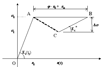
A graphical representation if the relation (11) is shown below where the first increase of the concrete stress is the segment O-A due to the instantaneous application of forces (initial elastic strain e0 = s0 / Ec(t0) in the first term of (11)). The horizontal segment A-B corresponds to the application of the free distortion due to creep ( s0 ⋅f(t,t0)/ Ec(t0) ) + shrinkage (ecs(t,t0) , from time t0 to t. Segment B-C is the second term of the (11) and is equivalent to a second elastic solution using the modulus adjusted for aging Ec*.
Stresses evaluation with AAEM method
We study a general cross section consisting of one or more concrete regions (also of different class and rheological characteristics), and a set of longitudinal bars however placed.
In a first phase (at time t0) section is subjected to the forces N, Mx, My to which correspond the strains a0, b0, c0 obtained by the iterative solution of the linear system (5), with elastic modulus Ecj and evalued at time t0. Elastic modulus of steel bars is always Es in the two pases. From a0, b0, c0 , we know the stresses (3) in every point of the section..
Δa0, Δb0, Δc0 from time t0 to final time t due to creep and shrinkage at constant values of N, Mx, My forces.
Now we apply to the section the forces N*, Mx*, My* such as to prevent any deformation caused by the rheological phenomena. For each concrete region j (no constrains with other regions and with and with bars) at time t the strains would be:
Δaj = fj(t,t0) ⋅ a0
Δbj = fj(t,t0) ⋅ b0 (12)
Δcj = fj(t,t0) ⋅ c0 + ecs j(t,t0)
To get the forces N*, Mx*, My* we perform the following numerical integrals with the adjusted modulus Ecj* = Ecj*(t,t0) :
N* = ∑j Ecj* Acj Δcj + ∑j Ecj* Sxcj Δbj + ∑j Ecj* Sycj Δaj
Mx* = ∑j Ecj* Sxcj Δcj + ∑j Ecj* Jxcj Δbj + ∑j Ecj* Jxycj Δaj (13)
My* = ∑j Ecj* Sycj Δcj + ∑j Ecj*Jxycj Δbj + ∑j Ecj* Jycj Δaj
or, in matrix notation:
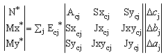
(14)
To restore the consistency of the deformations in the overall section we have to resolve the following system (5) with Ecj = Ecj*:
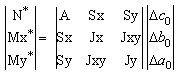 (15)
(15)
Known Δa0, Δb0, Δc0, the stress increase fro t0 to t is calculated with the equation (9) applied at point x,y of the region j:
Δsj = Ecj* Δecj - Ecj* ( fj ⋅e0 + ecs j)
where:
Δecj = Δa0 ⋅ x + Δb0 ⋅ y + Δc0
e0 = a0 ⋅ x + b0 ⋅ y + c0
The total strain in the section at time t is:
atot = a0 + Δa0 = χy tot
btot = b0 + Δb0 = χx tot (16)
ctot = c0 + Δc0 = eOrigine
So that neutral axis is given by:
atot x +btot y + ctot =0
Final stress in concrete are:
stot = st = s0 + Δs
Final stress in the bar i of coordinates xi , yi :
si tot = si 0 + Δsi
where:
si0 = Es ( a0 ⋅ xi + b0 ⋅ yi + c0 )
Δsi = Es (Δa0⋅ xi + Δb0⋅ yi + Δc0 )
To simplify the calculations in the case of cracking of section in the first loading (at time t0), we regard the compressed part of the section as not variable in form from t0 to t.
EM method
The fundamental relation of AAEM method is:
Ec*(t,t0) = Ec(t,t0) / (1+ c.f) (10)
EM method (Effective Modulus method) is a simplification of (10) where χ = 1:
Ec*(t,t0) = Ec(t,t0) / (1+f) (17)
Because of the uncertainty of the evaluation of the mechanical and rheological parameters the numerical difference between the two methods is minimal so it would seem useless the treatment carried out for AAEM method with respect to that leaner permitted by (17). In fact, the advantage of the AAEM method consists in the ability to take account of the shrinkage jointly with creep, while using the EM method the effect of the shrinkage must be calculated separately with different procedure (see (7.21) in §7.4.3 EC2 valid for beams but not for columns).