Ductility checks concern the following positions of sections of structures in seismic zones:
•within critical regions at the ends of all the beams (not secondary beams)
•within critical regions at the base of columns in DCM ductility class. (are excluded all the other critical areas of the columns on the upper floors on the first)
•within all critical region of columns in DCH ductility class.
•within critical regions of ductile walls
To respect the required local ductility in the above critical regions the curvature ductility factor μΦ must comply with the rule in §5.2.3.4 EC8:
μΦ ≥ 1,5 (2q0 - 1) if T1 ≥ TC (5.4) EC8
μΦ ≥ 1,5 [1+2(q0 - 1)] TC/ T1 if T1 < TC (5.5) EC8
where:
q0 basic value of the behaviour factor
T1 fundamental period of the building
TC period at the upper limit of the constant acceleration of the spectrum
For beams EC8 allows to replace (5.4)-(5.5) above control with the equations (5.11), (5.12).
For columns EC8 allows to replace (5.4)-(5.5) above control with the relation (5.15).
Building a moment-curvature diagram of the cross-section it is possible to evaluate μΦ so as to allow a direct check of the above (5.4)-(5.5).
In the figure below is shown such a diagram generated for a confined circular column in seismic zone.
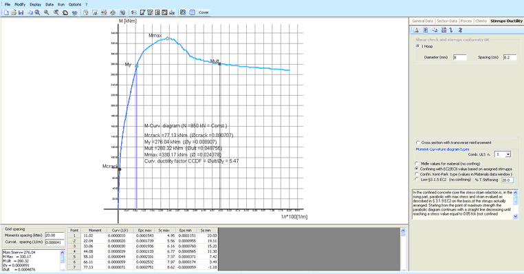
The moment-curvature diagrams can be of the following types:
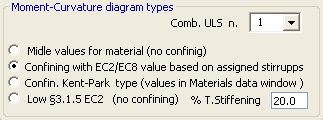
- The first option generate a diagram using for concrete and steel the same stress-strain relationship used for design check but with the substitution of the design values with the mean ones.
- The second option refers to a diagram that take in account the confining of concrete core by stirrups and the spalling of concrete cover at strain strength.
- The third type refers to a concrete stress-strain relation parabola-trapeze (Kent-Park Type) whose parameters are assigned in the Materials Library.
- Last type generate a diagram base on the relation shown in §3.1.5 EC2. You can take into account a certain percentage of tension stiffening.