This dialog window is opened if in General Data Tab you have selected the typology “Rectangular Section of column”.
For rectangular sections of the columns (the most common shape for columns in current applications) has been prepared a special type of calculation that, starting from a very quickly input (compared to that of the general sections), allows both the verification that the design of the reinforcement under biaxial bending and shear. It was also the possibility to perform the verification of the ultimate limit state of instability according to the simplified method of "nominal curvature" (§ 5.8.8 EC2).
The simplifying assumptions (but also the most common in practice) relate to the dialog window shown in the above figure are:
- Rectangular section refers to the axes X, Y coincident with x, y principal axes of inertia of concrete section;
- Longitudinal reinforcement is doubly symmetrical with respect to the principal axes of inertia x, y;
- Corner bars all have the same diameter and concrete cover (measured from the centre of the bars).
- Web bars arranged along X direction have the same diameter that can be different from the remaining bars; the same for the web bars arranged along Y direction.
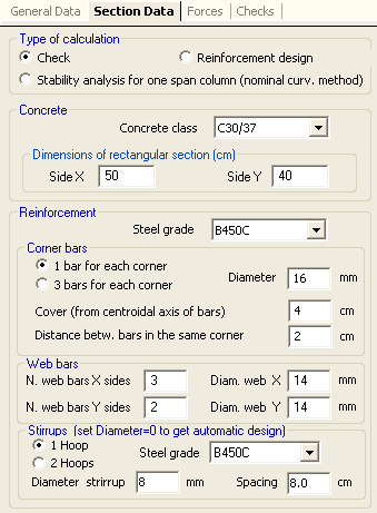
Below are listed each data to be entered in the above input window for check type of calculation:
•Concrete
in this frame can be assigned:
- concrete class: to choose in the corresponding drop-down menu between the classes assigned in the Materials Library.
- X side section: Measures in cm of the side parallel to the axis X.
- Y side section: Measures in cm of the side parallel to the Y axis
•Reinforcement
- steel grade: to choose in the corresponding drop-down menu between the classes assigned in the Materials Library.
- corner bars: number of bar per corner for each vertex of the section (one or three) and diameter [mm] of the bars to be used.
- cover: measured from centre of bars. No conformity check to EC2 rules - exposure class, strength class, etc. - is done by the program on these values.
- distance between bars in the same corner: min distance measured between perimeter of bars (only if you have select three bars per corner)
- web bars: number and diameter of intermediate bars between corners bars (along X and Y sides)
- Stirrups: choose the number, the diameter and the pitch of initial hoops and the steel grade of stirrup bars. After the first calculation you can modify the pitch or the number of hoops and cross-ties in the Stirrups-Ductility Tab. If you set the null value to the diameter (or to the pitch) the program performs the automatic design of stirrups reinforcement using the user default diameters assigned in code and reinforcement options.
When you first open this dialog window, the default option is that of a single bar for each vertex. You can then select the other option that take three bars for each vertex also staring at the net distance between the three bars.
|
© 2020 Geostru