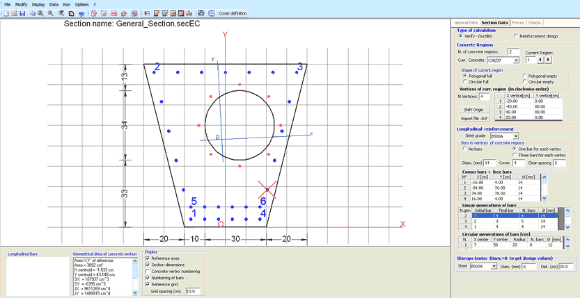
This dialog window is opened if in General Data Tab you have selected the typology “General Section”.
For this type of sections are expected checks for ULS and SLS combinations in uniaxial or biaxial bending and shear forces with or without axial force. The general sections may be formed by one or more regions of concrete (up to 20) each of which can have a polygonal shape or circular. Each region can be can be either full or empty (hollow sections). The bars can be assigned individually or automatically generated by the program on the basis of specific data shown below.
It is important to assign reinforcement only after having defined the number and the shape (circular or polygonal) of concrete regions. In order to accelerate the input of bars without the need to manually provide all the coordinates of the individual bars, may be assigned a bar at each vertex of the polygonal region by means of the appropriate button (1 or 3 bars for each vertex).
Any intermediate bars along the sides may be assigned by one or more linear generations of bars. In the example below the only coordinates assigned directly (in free bars grid) are those of the isolated bars n. 5, 6.
First you have to choose between the check option (assigning all geometrical and reinforcement data) and the design of reinforcement option (at geometrical data of concrete already assigned). In second case the program provides a tubular design distribution of longitudinal bars along the perimeter of concrete regions (that you can later freely change).
•Concrete Regions
In this frame the first input data is the number of concrete regions of the section (max 20). The above example section is formed by two concrete regions; the first is a full polygonal, the second is an empty circular one. The remaining data in this frame relate to each region (to select in the text box named Current Region) in which it is necessary to assign:
- Current concrete class: to choose in the corresponding drop-down menu between the classes assigned in the Materials Library.
- Shape of current region: to each region you must the pertinent polygonal or circular shape (full or empty).
- Vertices coordinates region: for polygonal regions these coordinate of vertices are to be assigned in clockwise order; for circular region the input data are the centre coordinates and the radius. Not allowed vertices in alignment with the two contiguous vertices (each straight side of polygonal regions must be defined only by the two end vertices).
- Shift origin: this optional command lets you to change all coordinate to a new reference system with origin in the concrete centroid of the section (particularly useful for imported sections from dxf file).
- Import file .dxf: this optional command lets you import all coordinates of vertices of a concrete region and the positions and diameters of bars contained in a file of type *. dxf built according to the details given in Import general section from dxf file.
•Longitudinal Reinforcement
For its definition it is necessary to assign:
- Steel grade: to choose in the corresponding drop-down menu between the classes assigned in the Materials Library.
- Bars in vertices of concrete regions: if you choose one or three bars in each vertex the program generate bars in all vertices of the polygonal section. The bars diameter of the first assignment is the default setting in the text box named "Diam.". The spacing between the three bars in each vertex is the default value in the text box named "Clear spacing". You can then change the diameter of the individual bars in the grid named "Corner bars + free bars": to change the diameter with a unique value just assign that value in the text box named "Diam.".
- Diam.: it is the default diameter [mm] of vertex bars (if present) initially set equal to the default value assigned in code and reinforcement options window. Changing this value all diameters of corner bars assume the same new value.
- Cover: it is the default value [cm] of vertex bars initially set equal to the default value assigned in code and reinforcement options window. This cover value is measured from the centre of bars. Changing this value all cover of bars assume the same new value. If bars are imported from a .dxf file (and then text box "bars in vertices of concrete regions" is set = 0) the cover value must be assigned directly by user as a mean value to define the effective width "d" of section in uniaxial or biaxial shear calculation and the cover c in eq. (7.11) EC2. No conformity check to EC2 rules - exposure class, strength class, etc. - is done by the program on these values.
- Clear spacing: this value is active only if user select the "Three bar for each vertex" option. The value refers to the minimum distance between perimeters of vertex bars. The change in its value has immediate effect on all the vertex bars.
- Corner bars + free bars: in the first rows of this grid are placed the coordinates and diameters of the vertex bas. In subsequent rows can be entered manually more isolated bars. In the above example have been directly assigned the free bars number 5 and 6.
- Linear generations of bars: in this grid you can assign a number of bars equidistant from each other and placed on the line joining any two bars already defined in the grid "Corner bars + free bars". In the above example have been assigned five linear generation: the first of which is between bar n.1 (Initial bar) and bar n. 2 (Final bar) and consists of n. 4 bars with diameter equal to 14 mm.
- Circular generations of bars: in this grid you can assign a number of equidistant bars placed on a circumference of a certain radius. In the above example we have assigned one circular generation by means the X centre, Y centre coordinates, the Radius, the number of bars and their diameters.
•Stirrups
doing a first verification calculation you may assign steel grade, diameter and pitch of only one initial virtual hoop. After the first calculation you can assign one or more hoops and cross-ties defined in the Stirrups-Ductility Tab. If you set the null value to the diameter (or to the pitch) the program performs the automatic design of the virtual hoop using the user default diameters in code and reinforcement options.
|
© 2020 Geostru