Seismic refraction surveys allow the interpretation of the subsoil stratigraphy through the physical principle of total refraction of a seismic wave that is incident on a discontinuity, detected between two bodies having different mechanical properties (refracting horizon).
The basic requirement to perform studies of seismic refraction is one for which the succession of layers to be investigated is characterized by increasing seismic velocities with increasing depth. In this way can be analyzed up to 4 or 5 different refracting horizons.
The surveys are based on the measurement of the travel times of the elastic waves for which, assuming the surfaces of discontinuity extended compared to the wavelength or, anyway, with weak curvature, the wavefronts are represented by the relative seismic rays. The analysis relies on Fermat's Principle and Snell's Law.
Fermat's Principle states that the ray travels the distance between the seismic source and receiver following the path for which the travel time is minimal. Given a plan separating two media with different elastic properties the seismic ray is the one that extends along a plan perpendicular to the discontinuity containing both the source and the receiver.
Snell's Law is a formula that describes the refraction modes of a seismic ray in the transition between two media characterized by different wave velocities or, equivalently, by different indices of refraction. The angle formed between the discontinuity surface and the seismic ray is called angle of incidence θi while that formed between the refracted ray and the normal surface is called refraction angle θr. The mathematical formulation is:
|
|
(1) |
Where v1 and v2 are the velocities of the two media separated by the discontinuity surface.
For v1 > v2 we have θi > θr and seismic refraction is not feasible because the refracted ray would be to tilt downwards.
For v1<v2 we have θi < θr and there is a limit angle of incidence for which θr = 90° and the refracted ray travels parallel to the discontinuity surface. The expression that defines the limit angle is:
|
|
(2) |
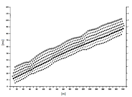
The easiest way to analyze the refraction data is to build a time-distance diagram in which the origin of the reference system is placed in correspondence of the generation source of the elastic waves. On the abscissa are shown the positions of the geophones and on the ordinate the times for the first arrivals. To geophones closest to the source arrive first the signals/impulses that have followed the direct path in a time T given by the relation:
|
|
(3) |
where xi is the distance between the energization (shot) point and the detection point.
The equation (3) represents a straight line passing through the origin of the time-distance axis and its angular coefficient allows to calculate the velocity V1 of the first medium as:
|
|
(4) |
The arrival times of the refracted rays, in the time-distance diagram, are arranged according to a straight line which will slope less than that of the direct waves.
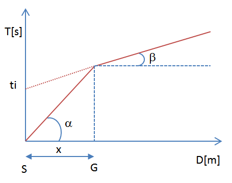
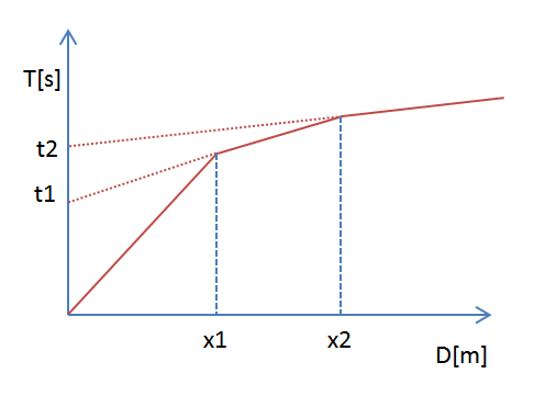
The time-distance curve tends to have a regular pattern according to a broken line whose vertices are called points of slope change and represent, physically, the condition of simultaneous arrival of the direct and refracted waves. For each of the segments identified is determined, therefore, the delay time ti that represents the difference between the time that the seismic ray takes to travel a segment at the speed of the layer in which is transmitted and the time it would take to travel along the horizontal component of that same segment at maximum speed reached in the whole refraction path.
Graphically, the delay time is given by the intersection of the straight line that includes a segment of the time-distance curve with the time axis.
Finally, from the knowledge of the times ti is possible to obtain the thickness of the refractors using the relation:
 (5)
(5)
In complex morphological situations can be used as a method of processing the General Reciprocal Method (GRM) discussed by Palmer in 1980.
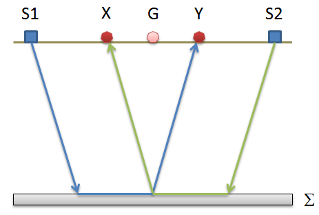
The method is based on the search of a virtual inter-geophone distance XY such that the seismic rays which start from symmetrical shot points compared to the geophone string (array), arrive at the geophone placed in position X and to the one placed in position Y coming from the same point of the refractor.
The first operational step is to build a time-distance diagram identifying in the seismograms obtained from field data the first arrivals of the seismic waves. To determine the optimal XY distance it is necessary to consider several shot points at the ends of the geophone line and within the geophone line as well. This procedure allows to identify more accurately the relative times to the same refractor, useful to characterize the traveltime curves, fundamental for the interpretation. In multi-layer interpretation, the generation of traveltime curves can use phantoming techniques to overcome the lack of data for some refractors.
From the construction of traveltime curves is possible to determine the velocity function according to the equation:
where TS1Y and TS2X are travel times of seismic rays to reach, respectively, from source S1 to X and from source S2 to Y while Ts1s2 is the travel time between the two shot points S1 and S2, external and symmetrical to the array (geophone string/line). Tv is the calculated time of a geophone G placed between X and Y, not necessarily coincident with the position of a geophone of the array (geophone string/line).
The calculation of the function Tv is performed for each value of XY between zero and half of the geophone string with variation equal to the actual distance between the geophones of the string. The best regression line of the velocity functions obtained allows to determine the optimal XY and the speed of the refractor that is derived from the angular coefficient.
Using the time-depth function it is possible to find the depth of the refractor expressed in units of time. The expression of this function is:
Where Vn is the velocity of the refractor.
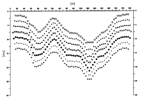
As is the case for the velocity function different time-depth functions are determined for the set of XY study values. Among the functions found, the one that has the highest articulation lies for the optimal value of XY.
Finally, it is possible to determine the thickness of the refractor at the positions of the geophones G using the relation:
|
|
(8) |
h represents the minimum depth of the geophone G therefore the morphology of the refractor is defined by the envelope of semicircles of radius h.
One of the main advantages of G.R.M. is that the conversion factor of the depth is relatively insensitive to inclinations up to about 20 °.
|
© Geostru