General Data
Enter the description of the work. The user can choose whether to include into the output report the description of the work using the specific checkbox.
Is is also possible to specify the area of intervention that will be displayed on a map. There are two possibilities to locate the area: Enter the WGS 84 coordinates or indicate the country and the city.
Find on map
The command connects GeoRock to the free application Geostru Maps that allows you to:
•find the elevations of assigned points
•plot longitudinal sections
•plot spot height plans
To create a 2D section you can proceed in two ways - assign points or create a polyline, (for the polyline confirm with a right click), search for the elevations using the command "Find Elevation" (wait..), run the command "Section".
After creating the 2D section with the above procedures, the section should be saved with the command "Export" in (*.sec) format. The section can be imported in GeoRock2D using the command "Import file from other GeoStru software" from the File menu.
Materials
The program has a database of materials that can be used to characterize each section of the slope.
For each material are defined two restitution coefficients (normal and tangential) the roughness, the frequency and the color.
The tangential coefficient determines the reduction of the velocity component parallel to the profile section during the impact. The normal coefficient is a measure of the velocity change, normal to the profile before and after the impact.
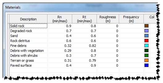
Obviously, while the vegetation influences the tangential coefficient, the stiffness of the material influence the normal coefficient.
The presence of vegetation with a height exceeding 1 m makes it difficult to determine the coefficients as its presence for the boulders that collapse for first can produce a behavior very close to that of a not very rigid material, but the boulders already collapsed alter the behavior of the boulders that come off after the first ones. The values suggested by the literature are not very uniform, so their validity should always be confirmed by practical applications on real cases.
The roughness of the surface (in m) is the maximum roughness/asperity of the section perpendicular to the slope in a range equal to the radius of the boulder. The roughness defines, in essence, the actual inclination of the slope in the point where impacts the boulder.
The frequency, expressed in meters, defines the interval associated with the i-th slope segment where the roughness periodically assumes the same value.
The Materials table is user-editable, so the user can assign any value to the normal and tangential restitution coefficients (Rn, Rt), to the roughness and also the user can associate a color to the material.
The user can customize the database by adding other materials to those already present or edit existing ones. It can also be assigned a color to a single segment of the profile: select the color with left click, with the mouse button pressed drag the selected color on the segment in the workspace.
Any changes made with the above operation will update automatically the Slope Vertices Table.
|
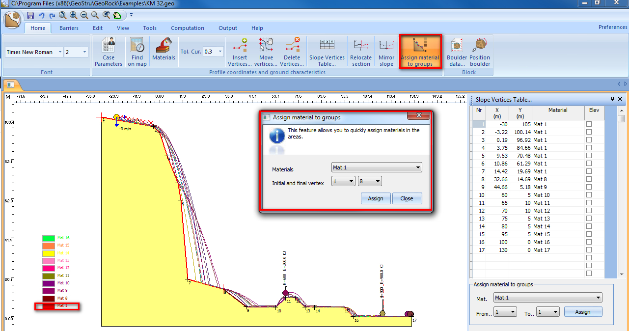
Slope vertices table
Selecting this command, on the right side of the work area you will see a table where you can change the geometric points that define the vertices of the profile.
Each vertex can be represented with its elevation, its partial distance and progressive distance selecting the corresponding checkbox "Elev". The program automatically updates the changes and with a right click the user can choose the option "Elev. all" to view the elevations of all vertices.
All data presented in the table can be copied or pasted using the commands "Copy" and "Paste" that can be selected from the drop-down menu activated with a right click.
This feature allows the user to quickly assign a material to areas of the profile, each area is defined by two vertices: the initial and final vertex.
To keep the change, it must confirmed with the "Assign" button. The last coordinate in the table doesn't need to be assigned. The command can also be run from the "Slope vertices table".
Boulder specific weight
Unit weight of the material constituting the boulder
Elasticity modulus
Elasticity modulus of the boulder
Initial x axis velocity [m/s]
X-component of the departure velocity; positive from left to the right
Initial y axis velocity [m/s]
Y-component of the departure velocity; positive from bottom up
Terminal limit velocity [m/s]
Value of the velocity reached by the boulder, at which the boulder is considered practically stationary and, therefore, the calculation is stopped
Shot area start abscissa [m]
Enter the value of the x-axis corresponding to the start position of the boulder
Shot area start ordinate [m]
Enter the value of the x-axis corresponding to the start position of the boulder
Throw step [m]
The analysis on multiple launches is performed by varying the position of the boulder starting from the initial position with step assigned
Number of trajectories
Enter the number of trajectories that you want to calculate from the initial position of the boulder
Elevation for boulder position
Enabling this option, the initial position of the boulder is shown together with the elevations
Deterministic analysis
Choosing the deterministic analysis the roughness at the point of impact remains constant
Statistical analysis
The statistical analysis differs from the deterministic analysis by the value assumed by the roughness. For this type of analysis the roughness is given random values
|
© GeoStru