The finite element problem consists of calculating the individual element stiffness matrices and vectors, and assembling them into the global stiffness matrix and force vectors. The set of simultaneous equations that this produces is then solved for the nodal displacements.
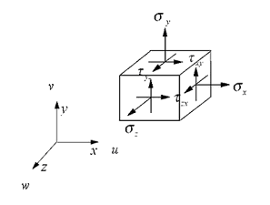
The stress vector σ and the strain vector ε are, respectively (Figure 14):
|
|
(5) |
|
|
|
|
Fig. 14. Components of the stress. |
The stress-strain relation is represented as:
|
|
(6) |
or as:
|
|
(7) |
where C is a symmetric matrix of material compliances, E is a symmetric matrix of material stiffness, and E=C-1. The components of the displacement vector u along x, y and z directions are u, v, and w respectively. The following sign convention is used: Positive y-coordinates and vertical forces are taken upward, i.e. parallel to the Y-axis. Positive x-coordinates and horizontal forces are taken to the right, i.e. parallel to the x axis. The vertical deflections are measured along the y-axis. A positive deflection therefore denotes an upward movement.
|
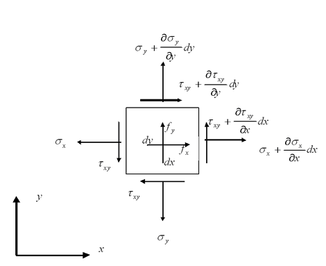
Fig. 15. Stresses and body forces that act on a plane differential element of constant thickness. |
|
© GeoStru Software