A body or domain is generally modeled using several quadrilateral regions connected to one another along one or more sides. The possibility of a common boundary between two regions requires that certain information be provided to insure that the nodes on this common boundary have the same numbers regardless of which region is being considered. The number of nodes on this boundary must be identical in number and must occupy the same relative position. This property is necessary to insure continuity across the element boundary.
|
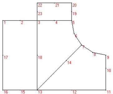
Fig. 6. A connected set of four quadrilateral regions. |
The determination of the connectivity data is probably best illustrated through an example such as the four-region body as shown in Fig.6. The boundary nodes coordinates are shown in Table 1 while the region's data (the number of divisions, the quadrilateral nodes numbering) is shown in table 2.
Table 1. Coordinates of boundary nodes.
Node |
X[m] |
Y[m] |
1 |
0 |
0 |
2 |
10 |
0 |
3 |
20 |
0 |
4 |
30 |
0 |
5 |
40 |
0 |
6 |
41.52 |
-7.65 |
7 |
45.86 |
-14.14 |
8 |
52.35 |
-18.48 |
9 |
60 |
-20 |
10 |
60 |
-27.5 |
11 |
60 |
-40 |
12 |
40 |
-40 |
13 |
20 |
-40 |
14 |
37 |
-23 |
15 |
10 |
-40 |
16 |
0 |
-40 |
17 |
0 |
-20 |
18 |
20 |
-20 |
19 |
40 |
5 |
20 |
40 |
10 |
21 |
30 |
10 |
22 |
20 |
10 |
23 |
20 |
5 |
Table 2. Region's data.
Region |
NRows |
Ncols |
Node 1 |
Node 2 |
Node 3 |
Node 4 |
Node 5 |
Node 6 |
Node 7 |
Node 8 |
1 |
25 |
15 |
16 |
15 |
13 |
18 |
3 |
2 |
1 |
17 |
2 |
25 |
25 |
13 |
14 |
7 |
6 |
5 |
4 |
3 |
18 |
3 |
25 |
25 |
13 |
12 |
11 |
10 |
9 |
8 |
7 |
14 |
4 |
15 |
25 |
3 |
4 |
5 |
19 |
20 |
21 |
22 |
23 |
|
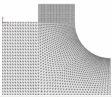
Fig. 7. The mesh. Delaunay triangulation. |
|
© GeoStru Software

