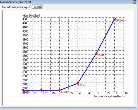
GFAS allows to construct complex geometries and analysis can be runned in different stages associated to different phases of construction. During the Staged construction analysis, the loads are increased from 0 to 1. As soon as the load parameter reaches the value of 1.0, the constructions stage is completed and the analysis of the current phase is completed, and go the the next phase of the construction. If a staged construction calculations finishes while the load factor is smaller than 1.0, the program will stop the analysis. The most likely reason for not finishing a construction stage is that a failure mechanism has occurred.
Table 9. Staged construction. Geometry and stages.
Stage 1 |
Stage 2 |
|
|
Stage 3 |
Stage 4 |
|
|
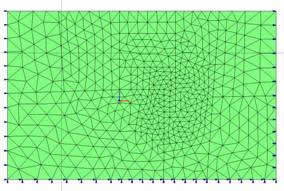
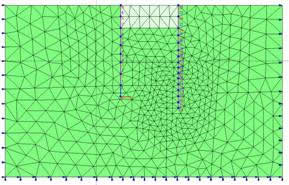
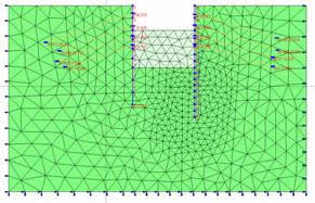
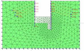
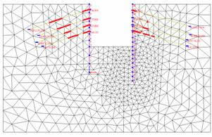
Table 10. Staged construction. Results: Shear stresses
Stage 2 |
Stage 3 |
|
|
Stage 4-Collapse |
|
|
|
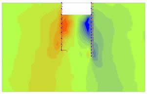

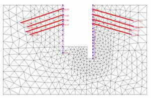
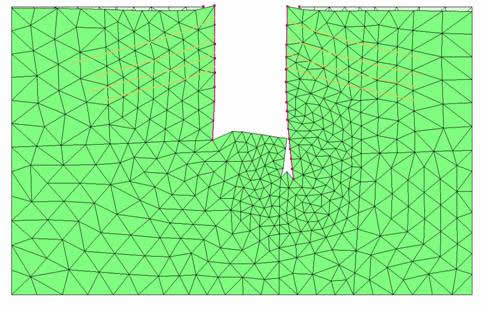
The computational example presented here describe an open excavation constructed in four stages. During the excavation process the soil is reinforced with walls and anchors as can be seen in table 9. The soil is modeled using the Mohr-Coulomb failure criteria and the elasto-plastic behavior is assumed for anchors. Only the gravitational loads and the excavation loads are taken into account during the construction process. Table 10 shows the distribution of the shear stresses for the stages 2 to 4 whereas in table 11 are depicted for each stage the variation of the bending moments in the walls. The collapse of the construction occurs at stage 4 as it can be seen on the Load-displacement graph depicted in Fig. 60. The deformation configuration at collapse of the construction is depicted in Fig. 61. At this stage also the anchors failed as it can be seen in Table 12.
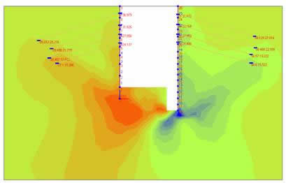
Table 11. Bending moments
Stage 2 |
Stage 3 |
|
|
Stage 4 |
|
|
|
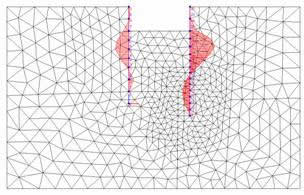
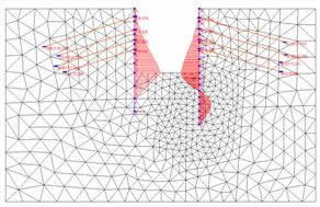
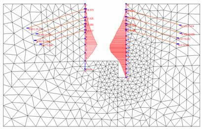
Table 12. Anchors yielded
Stage 3 –Partial yielding |
Stage 4- Fully Yielded |
|
|
|
Fig. 60 |
|
Fig.61. Deformed configuration at collapse. |
|
© GeoStru Software