A method for generating the calculation grid using the unstructured grid approach is presented.
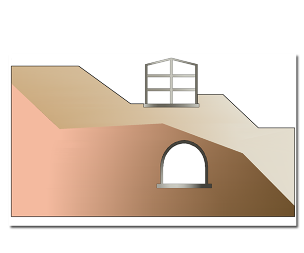
For simplicity of exposition, reference will be made to the figure below, which represents the volume of land to be modelled with GFAS.
The proposed method is structured in the following steps:

1.Construction of the calculation grid in Autocad.
2.Creation of a file (*.txt) to be imported into GFAS.
The first point specified reproduces the volume of terrain that needs to be simulated with GFAS by creating the ‘calculation grid’, i.e. sequences of nodes that define closed lines (regions).
For regions it is necessary that:
•are defined by closed polylines,
•the nodes of the grid coincide with the points of the polylines.
The sequence of nodes must be assigned according to the following conventions:
•from bottom to top;
•tracing the generic closed polyline in a counter-clockwise direction.
The choice of the position of the reference system is arbitrary.
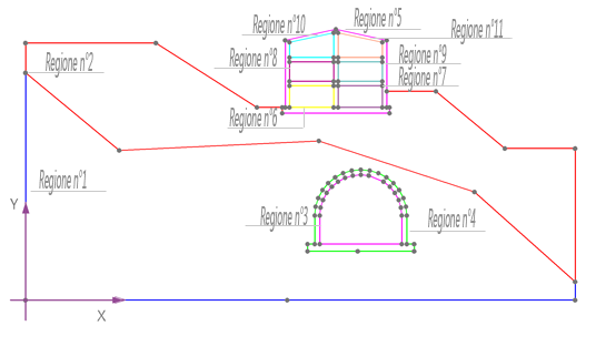
In the example, it was preferred to model the calculation grid, see figure below, with 11 differently coloured regions in order to make them recognisable. The nodes were marked with grey dots, the reference system was set with the origin coinciding with the position of node 1 of region 1.

The second step takes the form of the generation of a file (*.txt) containing the structure of each region: identification number, number of nodes in the sequence of which it is defined, and coordinates of each node in the region with respect to the reference system.
In this specific case, the structure of the text file (*.txt) is as follows:
‘GFAS FILE‘,’‘,’’ (This is a generally valid string, every *.txt file carries this character sequence)
‘LAYER‘, “1”,9,’’ (Indicates that region 1 is defined by 9 nodes)
‘VERTEX’, “1”,0.00,0.00 (from this point onwards the coordinates of the vertices are given)
‘VERTEX‘,’9’,0.00,15.0875
‘LAYER‘, “2”,17,’’ (designates that region 2 is defined by 17 nodes)
‘VERTEX‘,’1’,0.00,31.4399
‘VERTEX‘,’17’,0.00,35.567
‘LAYER‘, “3”,24,’’ (specifies that region 3 is defined by 24 nodes)
‘VERTEX‘,’1’,38.8787,6.7509
‘VERTEX‘,’24’,38.8787,7.7509
‘LAYER‘, “11”,4,’’ (denotes that region 11 is defined by 4 nodes)
‘VERTEX‘,’1’,43.0947,33.5566
‘VERTEX‘,’4’,43.0947,36.9911
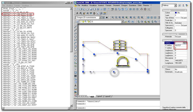
The figure shows the Autocad working environment and highlights the point where the coordinates of the points of the polylines to be entered in the text file.

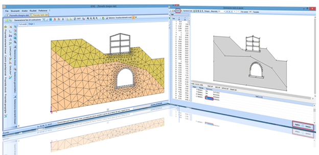
In GFAS, from the ‘Unstructured Mesh Generation’ environment by clicking on the ‘Import’ command, it is possible to open the file (*.txt) created according to the above instructions. The result of the problem analysed is shown below: at this point it is necessary to assign the curve type ‘interface or hole’ (if there are gaps, assign hole). The procedure is concluded by selecting the commands, Apply and Generate, in succession with the click of the mouse, from which the calculation mesh will be generated.

|
© GeoStru Software