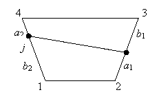
Let us consider the truss element connected to points arbitrarily located along edges of a plane four-noded element (Fig.30).
|
Figure 30. |
The deformational-stiffness relation for the truss element is written as:
|
(114) |
where k’, u’ and r’ represents the stiffness matrix, displacement vector and nodal force vector associated with the degrees of freedom of nodes i and j of the truss element:
|
(115) |
With displacements linearly interpolated along edges of the quadrilateral the displacement transformation for d.o.f. of the truss element can be written in function of the displacements of the plane element nodes (u), via transformation matrix T as:
|
(116) |
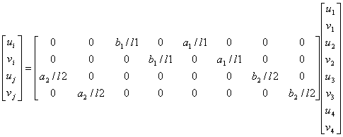
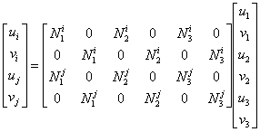
Where the transformation matrix T contains terms like those in the eq. (108). For the case depicted in the Figure 30 the displacement transformation relation can be detailed in the matrix form as:
|
(117) |
By transformation, ![]() and
and ![]() of the truss element are to be converted to
of the truss element are to be converted to ![]() and
and ![]() which are associated with the degrees of freedom of the four corner nodes of the quadrilateral. Thus,
which are associated with the degrees of freedom of the four corner nodes of the quadrilateral. Thus, ![]() becomes
becomes ![]() and
and ![]() becomes
becomes ![]() :
:
|
(118) |
After this transformations the nodal force vector and stiffness matrix can be directly added to the corresponding arrays of the quadrilateral or assembled into the structure. The nodes i and j of the truss element and their d.o.f. are not explicitly present, we can say that d.o.f. of the bar element are constrained to follow d.o.f. of the quadrilateral. Similar relations can be obtained in the case when the truss element is mapped into the higher order plane elements. In this case the nodal displacements of the truss element are quadraticaly interpolated from translational d.o.f of plane element nodes. For instance assuming the six-noded higher order element crossed by the truss element the displacement transformation relation is:
|
(119) |
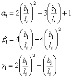
and in which
|
(120) |
|
(121) |
|
(122) |
where:
|
(123) |
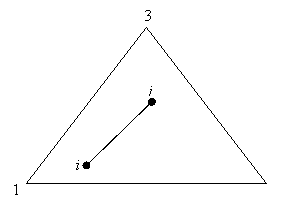
This approach can be applied even when the truss element nodes fall inside the plane element. For instance considering the truss element with nodes i and j within the triangular 3-noded element like in the Figure 31.
|
Figure 31. |
The displacements of the element nodes can be obtained throughout shape functions of the “parent element” as:
|
(124) |
where ![]() , k=1,2,3 represents the shape functions for the triangular element computed for each node coordinates of the truss element. Hence the stiffness matrix and nodal force vector are obtained in this case:
, k=1,2,3 represents the shape functions for the triangular element computed for each node coordinates of the truss element. Hence the stiffness matrix and nodal force vector are obtained in this case:
|
(125) |
Where the transformation matrix in this case is:
|
(126) |
Similar transformation matrices can be obtained when quadrilateral or higher order plane elements are used. The shape functions are computed in truss element nodes with known coordinates. Usually these coordinates are given in the global coordinates whereas the shape functions of the plane elements are given in the natural coordinate systems. Therefore some transformations are also necessary to obtain the coordinates of the truss element nodes in the natural coordinates. These transformations are based on the isotropic character of the plane element used. For triangular elements the global coordinates (x, y) and the natural coordinates (ξ, η). are relationed as:
|
(127) |
in which xi, yi (i=1,2,3) represents the coordinates of the triangular element nodes and the shape functions Ni have the following expressions represented in the natural coordinate system as:
|
(128) |
For the known x, y coordinates we can obtain the corresponding natural coordinates by solving the following system of equations:
|
(129) |
Similarly we can obtain the natural coordinates in the case when the plane element is quadrilateral.
© GeoStru Software
