2.2.1 - Prior calculation of the thickness hr
For the calculation of the net limit pressure, the conventional thickness hr should first be calculated according to the method described in Table 10.
|
|
ELU |
ELS almost-permanent ELS characteristic |
Strip footing of width B |
|
|
|
|
|
||
Circular footing of diameter B |
|
|
|
|
|
||
Spread footing of width B and length L |
|
|
|
|
|
Table 10: Determination of thickness hr [D.2.2 (2)]
(26) The formula given in the standard for h in the case of a spread footing using the eccentricity of the load is incorrect. Table 10 takes the correction into account.
2.2.2 - Calculation of the equivalent net limit pressure
From the pressiometric results and for a heterogeneous soil (27), the equivalent net limit pressure is calculated according to the following formula:
 [Formula D.2.2] *
With:
pl;k;i*: the characteristic or representative value of the net limit pressure in the layer of land between D and D + hr (Figure 2);
D: depth of the base of the footing relative to the natural terrain rating after the work has been completed.
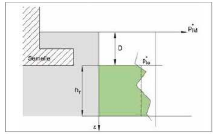
Figure 2: Determination of the net equivalent pressure limit ple*
* This formula can be expressed mathematically correctly as ![]() : where hr;i is the thickness of the layer of limit pressure pl;k;i.
: where hr;i is the thickness of the layer of limit pressure pl;k;i.
(27) As an indication, a formation may be considered homogeneous if it is composed of a soil of a single nature and if the maximum limit pressures measured in that formation do not exceed twice the minimum limit pressures. This estimate cannot be used in the case of penetrometric tests due to the irregularity of the diagrams.
When the ground under the foundation consists of the same soil (or soils of the same type and comparable net limit pressures) to a depth of at least 1,5B and the representative pressiometric profile of the soil slice can be defined linearly as (Figure 3):
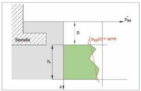
Figure 3: Determination of the net equivalent limit pressure ple*
![]()
In this case, the equivalent limit pressure is taken equal to the value of plM* linearized at depth ![]() [Item 2 of Annex E.2 of Issue 62]
[Item 2 of Annex E.2 of Issue 62]
Note: For low ple* values (less than 0.2 MPa for clays and silts and 0.3 MPa for sands), it is necessary to verify by a special study that the bearing of the soil under the foundation is perennial.
2.2.3 - Calculation of the equivalent flush-mounting height De
In order to calculate the pressiometric lift factor kp, it remains to evaluate the influence of the equivalent flush-mounting height De (Figure 4) which is determined as follows:
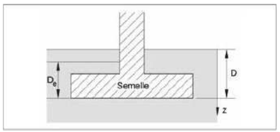
Figure 4: Determination of equivalent flush-mounting De
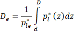 [Formula C.2.1]
With:
Pl* : value of the net limit pressure;
ple* : value of the equivalent net limit pressure calculated for almost-permanent ELS share combinations [C.2 (2)].
In general, d = 0 unless the surface soil properties are very poor(28). In this case, it is possible to safely neglect the soil thickness concerned. It is possible in certain special cases to have De > D, for example when the value of pl* above the footing is greater than that under the footing.
(28) The calculation of De is carried out with the values of the boundary pressures between d and D of the land in place, except in the rare case where the backfilled ground protrudes significantly (in relation to the size of the foundation of the footing right-of-way, of the order of several B). In this particular case, it is then possible to use the boundary pressures of the backfilled ground.
2.2.4 - Calculation of the pressiometric bearing factor kp
The value of kp depends on the shape of the footing and its recess. The following formulas may be applied only(29) if ![]() beyond
beyond ![]()
• If B / L = 0 (strip footing) or B / L = 1 (square or circular or spread footings of diameter B) then k is determined by the following relationship:
![]() [Form D.2 .3.1 ]
[Form D.2 .3.1 ]
(29) On the other hand, cases where 1,5 B < De < 2 B are outside the scope of use of this guide since it would then be a semi-deep foundation.
The coefficient kp0 is given in the special cases of strip or square footings. Table 11 gives the values of the parameters a, b, c and kp0 to calculate ![]()
(bearing factor for a strip footing) ![]() (bearing factor for a circular or spread footings). Figure 5 also shows how to graphic way.
(bearing factor for a circular or spread footings). Figure 5 also shows how to graphic way.
• If B / L is different from 0 or 1 (spread footings) kp is calculated by combining these two special cases. The relationship to be used is then as follows:
![]() [Form D.2 .3.2 ]
[Form D.2 .3.2 ]
For a spread footings, it will therefore necessarily be necessary to calculate the terms ![]() and
and ![]() beforehand.
beforehand.
Soil category* |
Lift factor variation curve |
kp expression |
|||||
a |
b |
c |
|
|
|||
Clays and silts |
Spinning footing
|
Q1 |
0,2 |
0,02 |
1,3 |
0,8 |
1,022 |
Square footing
|
Q2 |
0,3 |
0,02 |
1,5 |
0,8 |
1,123 |
|
Sands and gravels |
Spinning footing
|
Q3 |
0,3 |
0,05 |
2 |
1 |
1,393 |
Square footing
|
Q4 |
0,22 |
0,18 |
5 |
1 |
1,580 |
|
Chalks |
Spinning footing
|
Q5 |
0,28 |
0,22 |
2,8 |
0,8 |
1,517 |
Square footing
|
Q6 |
0,35 |
0,31 |
3 |
0,8 |
1,768 |
|
Marl and marl-limestone Weathered rocks |
Spinning footing
|
Q7 |
0,2 |
0,2 |
3 |
0,8 |
1,399 |
Square footing
|
Q8 |
0,2 |
0,3 |
3 |
0,8 |
1,598 |
|
* The choice of the soil category is to be made in accordance with Annex A of standard NF P94-261. The intermediate soils will be attached either to clays and silts (silt clays, clay silts and clay sands) or to sands and gravel (clay sands, loamy sands and silts, sandy) [Table D.2.3 NOTE 1]. |
|||||||
Table 11: Determination of pressiometric bearing factor [Table D.2.3]
The value of kpmax is given as an indication, it can be considered as a maximum limit not to be exceeded. It can only be achieved in the case of a semi-deep foundation (outside the field of employment of this guide).
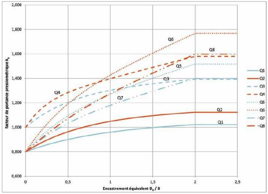
Figure 5: Values of the lift factor ![]() as a function of the relative underfootfall De / B [Figure D.2.3]
as a function of the relative underfootfall De / B [Figure D.2.3]
Table 12 makes it possible to visualize the steps of the calculation of the load-bearing factor ![]() according to the shape of the footing.
according to the shape of the footing.
|
Strip footing of width B |
Spread footing of width B and length L |
Square footing on side B or circular footing with diameter B |
1 |
Determination of
for
(Table 11) |
Determination of Determination of
(Table 11) |
Determination of
(Table 11) |
2 |
Calculation of |
Calculation of |
Calculation of |
3 |
Calculation of
|
Calculation of
Calculation of |
Calculation of
|
4 |
|
|
|
Table 12: Calculation steps for the determination of the pressiometric load-bearing factor