2.3.1 - Prior calculation of the thickness hr
For the calculation of the thickness hr, the approach is identical to that of the pressiometric method. Reference should be made to paragraph 2.2.1 of this chapter.
2.3.2 - Calculation of equivalent peak resistance
The equivalent peak resistance is calculated according to the following formula:
![]() [Formula E .2.2 .1]
[Formula E .2.2 .1]
With ![]() corrected peak resistance, obtained:
corrected peak resistance, obtained:
• by calculating the average value qcm Resistance of smoothed tip between depths D and D + hr;
• by clipping beforehand, if necessary, the diagram qc(z) at the value 1.3 qcm.
D is the depth of the base of the footing relative to the natural terrain rating after the work has been completed (Figure 6).
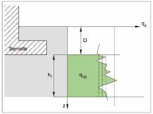
Figure 6: Determination of the equivalent peak resistance qce
The thickness hr shall be determined by the method described in paragraph 2.2.1. of this chapter.
Note: For values of qce low (less than 1 MPa for clays and silts and 1.5 MPa for sands), it is necessary to verify by a special study that the bearing of the soil under the foundation is perennial.
2.3.3 - Calculation of the equivalent flush-mounting height De
In order to calculate the penetrometric lift coefficient kc, it remains to evaluate the influence of the equivalent flush-mounting height De (Figure 7) which is determined as follows:
![]() [Formula C .2.2]
[Formula C .2.2]
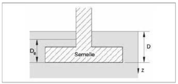
Figure 7: Determination of equivalent flush-mounting De
In general, d = 0 unless the mechanical properties of the soil on the surface are very mediocre(30). In this case, it is possible to safely neglect the soil thickness concerned. It is possible in some special cases to have De > D, for example when the value of qcc above the footing is greater than that under the footing.
(30) The calculation of De is carried out with the values of the peak resistances between d and D of the ground in place, except in the rare case where the backfilled ground protrudes significantly laterally (in relation to the size of the foundation of the footing right-of-way, of the order of several B). In this particular case, it is then necessary to use the pointed resistors of the backfilled ground.
With
qcc: corrected peak resistance value;
qce: the value of the equivalent penetrometric peak resistance calculated for combinations of actions at almost-permanent ELS [C.2 (2)].
2.3.4 - Calculation of the penetrometric lift factor kc
The value of kc depends on the shape of the footing and its embedding. The following formulas may be applied only(31) if ![]() , beyond kc = kmax .
, beyond kc = kmax .
(31) On the other hand, cases where 1,5 B < De < 2 B are outside the scope of use of this guide since it would then be a semi-deep foundation.
• If ![]() (strip footing) or
(strip footing) or ![]() (square or circular footing of diameter B) then kc is determined by the following relationship:
(square or circular footing of diameter B) then kc is determined by the following relationship:
![]() [Form E.2 .3.1 ]
[Form E.2 .3.1 ]
The coefficient kc0 is given in the special case of spinning or square footings. Table 13 gives the values of parameters a, b, c and kc0, to calculate ![]() (bearing factor for a strip footing) and
(bearing factor for a strip footing) and ![]() (bearing factor for a spread footings). Figure 8 also makes it possible to determine them graphically.
(bearing factor for a spread footings). Figure 8 also makes it possible to determine them graphically.
• If B / L is different from 0 or 1 (spread footings) kc is calculated by combining these two special cases. The relationship to use is as follows:
![]() [Form E.2 .3.2 ]
[Form E.2 .3.2 ]
For a spread footings, it will therefore necessarily be necessary to calculate the terms ![]() and
and ![]() beforehand.
beforehand.
Soil category* |
Lift factor variation curve |
kc expression |
|||||
a |
b |
c |
|
|
|||
Clays and silts |
Spinning footing
|
Q1 |
0,07 |
0,007 |
1,3 |
0,27 |
0,348 |
Square footing
|
Q2 |
0,1 |
0,007 |
1,5 |
0,27 |
0,378 |
|
Sands and gravels |
Spinning footing
|
Q3 |
0,04 |
0,006 |
2 |
0,09 |
0,141 |
Square footing
|
Q4 |
0,03 |
0,02 |
5 |
0,09 |
0,160 |
|
Chalks |
Spinning footing
|
Q5 |
0,04 |
0,03 |
3 |
0,11 |
0,210 |
Square footing
|
Q6 |
0,05 |
0,04 |
3 |
0,11 |
0,240 |
|
Marl and marl-limestone Weathered rocks |
Spinning footing
|
Q7 |
0,04 |
0,03 |
3 |
0,11 |
0,210 |
Square footing
|
Q8 |
0,05 |
0,04 |
3 |
0,11 |
0,240 |
|
* The choice of the soil category is to be made in accordance with Annex A of standard NF P94-261. The intermediate soils will be attached either to clays and silts (silt clays, clay silts and clay sands) or to sands and gravel (clay sands, loamy sands and silts). |
|||||||
Table 13: Determination of penetrometric lift factor [Table E.2.3]
The value of kcmax is given as an indication, it can be considered as a maximum limit not to be exceeded. It can only be reached in the case of a semi-deep foundation (outside the scope of use of this guide).

Figure 8: Values of lift factor kc as a function of relative underrun De / B [Figure E.2.3]
Table 14 makes it possible to visualize the steps of the calculation of the lift factor kc according to the shape of the footing.
|
Strip footing of width B |
Spread footing of width B and length L L |
Square footing on side B or circular footing of diameter B |
1 |
Determination of
(Table 13) |
Determination of
Determination of (Table 13) |
Determination of (Table 13) |
2 |
Calculation of |
Calculation of |
Calculation of |
3 |
Calculation of |
Calculation of Calculation of |
Calculation of |
4 |
|
|
|
Table 14 : Calculation steps for the determination of the penetrometric contribution factor