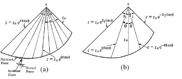
In using the friction circle method or the method of slices, the distribution of forces along the failure arc or on both sides of a slice must be assumed arbitrarily.
This diffi culty can be overcome if a logarithmic spiral is used as a failure surface. No matter what the magnitude of normal forces on the failure surface may be, the property of the logarithmic spiral is such that the resultant of the normal and frictional forces always will pass through the origin of the spiral. Consequently, when a moment is taken about the origin, the combined effect of normal andfrictional forces is nil, and only the weight and cohesion moments need to be considered. This logarithmic-spiral method was fi rst suggested by Taylor (1937) for stability analysis.
Fundamental Principles and Advantages
•This method overcomes the difficulty of having to arbitrarily assume the distribution of forces along the failure surface. This is a common problem in other limit equilibrium methods, such as the friction circle method or the method of slices.
•The key property of the logarithmic spiral is that the resultant of the normal forces and friction forces always passes through the origin of the spiral.
•Consequently, when calculating the moment about the origin of the spiral, the combined effect of the normal and friction forces is zero. This greatly simplifies the calculation, as only the moments due to the soil weight and cohesion remain to be considered.
•This characteristic makes it a benchmark (or "yardstick") for verifying the accuracy of other analysis methods, given that it satisfies moment equilibrium without further assumptions beyond the logarithmic spiral shape of the failure surface.
Logarithmic Spiral Equation
The equation of a logarithmic spiral in polar coordinates is expressed as: r = ro e(θ * tan φ)
Where:
•r is the radius from the origin to the logarithmic spiral.
•r₀ is the initial radius.
•θ is the angle (in radians) between the initial radius and the radius r. The length of the radius increases if θ is measured clockwise; it decreases if measured counter-clockwise (θ is negative).
•φ is the angle of internal friction of the soil. The shape of the logarithmic spiral is controlled by φ. A line normal to the logarithmic spiral always forms an angle φ with the radial line.
The origin of the logarithmic spiral is located by means of two arbitrary angles, t and z.

Characteristics of a logarithmic spiral
When using the friction circle method or the method of slices, the distribution of forces along the failure arc or on the sides of a slice must be assumed arbitrarily. This difficulty can be overcome if a logarithmic spiral is used as the failure surface.
Regardless of the magnitude of the normal forces on the failure surface, a key property of the logarithmic spiral is that the resultant of the normal and frictional forces always passes through the origin of the spiral. Consequently, when calculating the moment about the origin, the combined effect of the normal and frictional forces is zero, and only the moments due to weight and cohesion need to be considered. This logarithmic spiral method was first proposed by Taylor (1937) for stability analysis.
How to Set Up a Logarithmic Spiral Slip Surface in Slope
1.Define the Geometry and Stratigraphy Define the geometry of the cross-section and its stratigraphy.
2.Define the coordinates for the upper and lower vertices and the number of rows for the slip surface grid. It's possible to define these parameters graphically by switching to a circular surface, drawing the grid of centers, and then returning to the generic surface option: the software will store this data.
3.Define the coordinates for the point through which the logarithmic spirals must pass. A point that is suitable for the section's profile should be entered.
4.Press Generate. Optionally, enable the "Fit spiral to profile" setting to eliminate any portions of the spiral that fall outside the cross-section.
5.If necessary, you can refine the analysis by increasing the number of points that define the spirals, the number of rows and columns in the grid of centers, or the coordinates of the grid itself.
6.Run the analysis/calculation.
© GeoStru