The sliding check, in the case of walls reinforced with the Soil Nailing technique, can be considered as a particular case of the global stability check, which may occur when a weak layer lies beneath the reinforced block. According to the American guidelines FHWA-NHI-14-007, the sliding check can be performed with reference to the mechanism indicated in Figure 6.
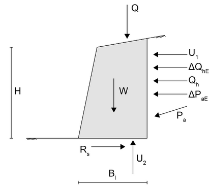
Fig. 6 – Failure mechanism used to perform the sliding check, in accordance with the American guidelines FHWA-NHI-14-007.
The actions indicated in the diagram in Figure 6 are as follows:
•![]() : Soil pressure due to its own weight, in terms of effective stresses, under static conditions.
: Soil pressure due to its own weight, in terms of effective stresses, under static conditions.
•![]() : Increase in soil pressure in terms of effective stresses due to seismic effects.
: Increase in soil pressure in terms of effective stresses due to seismic effects.
•![]() : Weight of the potentially unstable wedge.
: Weight of the potentially unstable wedge.
•![]() : Resultant of loads applied on the ground surface.
: Resultant of loads applied on the ground surface.
•![]() : Resultant of horizontal stresses acting on the vertical wall, due to loads applied on the ground surface, under static conditions.
: Resultant of horizontal stresses acting on the vertical wall, due to loads applied on the ground surface, under static conditions.
•![]() : Increase in
: Increase in ![]() due to seismic effects.
due to seismic effects.
•![]() : Resultant of neutral pressures acting on the vertical wall.
: Resultant of neutral pressures acting on the vertical wall.
•![]() : Water uplift.
: Water uplift.
•![]() : Resistance against sliding.
: Resistance against sliding.
It is necessary to note that the position in which these forces are represented in Figure 6 is entirely indicative because the check is performed using equilibrium equations in the horizontal and vertical directions, while rotational equilibrium is not imposed; therefore, the arms do not come into play. The weight W is calculated by multiplying the weight of the unit volume of the block by the corresponding area, while Q is calculated as the sum of the resultants of all vertical loads applied to the ground surface within the width Bl. ![]() is calculated as the resultant of horizontal stresses due to loads applied to the ground surface, referring to the theory of elastic half-space. This value refers to the static condition and is therefore a function of the coefficient of active earth pressure Ka. The following equation is used for the calculation of
is calculated as the resultant of horizontal stresses due to loads applied to the ground surface, referring to the theory of elastic half-space. This value refers to the static condition and is therefore a function of the coefficient of active earth pressure Ka. The following equation is used for the calculation of ![]() :
:
|
|
(17) |
Where ![]() is the counterpart of
is the counterpart of ![]() , but referred to the pseudo-static condition and is therefore calculated based on the coefficient of active earth pressure KaE. The other forces are calculated using the following equations:
, but referred to the pseudo-static condition and is therefore calculated based on the coefficient of active earth pressure KaE. The other forces are calculated using the following equations:
|
|
(18) |
This equation is valid in the case of homogeneous and dry soil. In the presence of a water table, the equation is modified, taking into account the weight of the unit volume lightened for the portions of soil below the water table level. The value of H1 represents the height of the internal vertical wall of the potentially unstable wedge. Furthermore:
|
|
(19) |
Where ![]() is analogous to
is analogous to ![]() , with the difference that the calculation is performed using the coefficient KaE instead of Ka. Similarly to the checks mentioned earlier,
, with the difference that the calculation is performed using the coefficient KaE instead of Ka. Similarly to the checks mentioned earlier, ![]() and
and ![]() are considered separately (instead of directly considering
are considered separately (instead of directly considering ![]() ), allowing the use of different amplification coefficients if an empirical approach is desired. The resultant of neutral pressures
), allowing the use of different amplification coefficients if an empirical approach is desired. The resultant of neutral pressures ![]() is calculated using the following equation:
is calculated using the following equation:
|
|
(20) |
Where d1 is the portion of H1 below the water table. This equation holds under the assumption that, in the presence of an inclined ground surface, the water table is parallel to the ground surface, and there is a filtration movement parallel to it. The water uplift ![]() takes the following expression:
takes the following expression:
|
|
(21) |
The resistance against sliding is instead equal to:
|
|
(22) |
Where ![]() and
and ![]() are respectively the cohesion and angle of shear resistance of the foundation soil.
are respectively the cohesion and angle of shear resistance of the foundation soil.
The sliding check involves ensuring that the corresponding safety factor is greater than unity. This safety factor is defined as follows:
|
|
(23) |
In which
|
|
(24) |
Finally, it is necessary to note that the check is performed with reference to a potentially unstable wedge with a width equal to ![]() . This width can be assumed or calculated. In the latter case, the following options are considered for the calculation of
. This width can be assumed or calculated. In the latter case, the following options are considered for the calculation of ![]() :
:
|
|
(25) |
|
|
(26) |
In this equation, ![]() represents the depth of the first nail relative to the top of the wall, while
represents the depth of the first nail relative to the top of the wall, while ![]() and
and ![]() are respectively the length and inclination of the same nail.
are respectively the length and inclination of the same nail.