The internal stability check must be carried out with reference to potential failure surfaces that extend through the soil and some or all of the reinforcements (Fig. 3a). The soil strength can be considered as either frictional and/or cohesive, depending on the soil type and whether the loading rate may result in drained or undrained conditions. If the failure surface intersects some or all of the reinforcements, the strength of the reinforcements mobilized in the portion of the soil beyond the failure surface also contributes to stability. In the following, internal checks are performed using the method proposed by Sheahan & Ho (2003), as suggested by the American guidelines FHWA-NHI-14-007. This method involves verifying internal stability by imposing the equilibrium condition of forces acting on the potentially unstable wedge of soil, delimited by the planar failure surface shown in Fig. 2 and inclined at an angle β. The resulting expression for the factor of safety in internal verification is given by:
|
|
(1) |
in which
|
|
(2) |
The parameters indicated in these equations have the following meanings:
•![]() : Effective cohesion of the soil
: Effective cohesion of the soil
•![]() : Shear resistance angle of the soil
: Shear resistance angle of the soil
•![]() : Weight of the potentially unstable soil wedge
: Weight of the potentially unstable soil wedge
•![]() : Resultant of external loads applied to the potentially unstable soil wedge
: Resultant of external loads applied to the potentially unstable soil wedge
•![]() : Water pressure
: Water pressure
•![]() : Horizontal seismic coefficient
: Horizontal seismic coefficient
•![]() : Vertical seismic coefficient
: Vertical seismic coefficient
•![]() : Number of nails
: Number of nails
•![]() : Resistance of the i-th nail mobilized at the failure surface.
: Resistance of the i-th nail mobilized at the failure surface.
In the case where the soil is not homogeneous, the values of shear strength parameters are averaged based on the thickness of the respective layer.
The value of R is calculated according to the American guidelines using the following equation and as depicted in Figure 4.
|
|
(3) |
Where ![]() and
and ![]() represent the resistance against tensile failure and pullout failure of the nail, respectively. The expressions for the calculation of
represent the resistance against tensile failure and pullout failure of the nail, respectively. The expressions for the calculation of ![]() and
and ![]() are provided in the subsequent sections, dedicated to their respective verifications.
are provided in the subsequent sections, dedicated to their respective verifications.
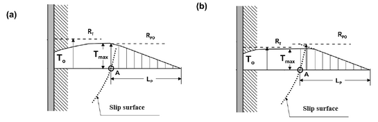
Fig. 4 – Tensile forces in the reinforcement: a) pullout resistance governs; b) structural resistance of the nail governs (American guidelines FHWA-NHI-14-007).
The internal stability check (Eq. 1) is performed for each excavation phase, considering the resistance provided by the installed nails and the excavation depth reached in each respective phase. For each excavation phase, the planar failure surface is always assumed starting from the maximum excavation depth reached.