The data relevant to the ground geometry is necessary for the definition of the topographic profile of the ground. The environment for the management of the ground profile is the following:
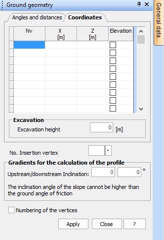
Data entered by coordinates
Enter the coordinates of vertices which define the profile with regard to a fixed reference system. The vertices must be entered from downstream to upstream in terms of x-z coordinates. The coordinates must be expressed in m. The inclination of the upstream and downstream profile must be also entered. It is possible to view the numbers of the vertices.
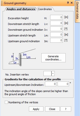
Data entered by angles and distances
•Excavation height (H): Expressed in m, it represents the part which will remain above ground after the execution of the excavation.
•Downstream stretch length (LV): Expressed in m; it is necessary to carefully estimate this quantity especially for the analysis of the global stability and for the analysis of the filtration phenomenon (Order of magnitude = 1/2 times the excavation height).
•Downstream ground inclination (IV): Expressed in degrees (depends mainly on the topographic conditions of the problem).
•Upstream stretch length (LM): Expressed in m (the same considerations made for the length of the downstream stretch are valid).
•Upstream ground inclination (IM): Expressed in degrees (its value is based on the topographic configuration of the case under examination).
•Gradients for the calculation of the profile: Expressed in degrees, both upstream and downstream, they represent the values used by the software for the calculation of the thrust with inclined profile; their value is based on the topographic configuration of the case under examination, but it must be specified that the formulas used for the calculation of the active and passive thrusts generally have validity limitations precisely on such parameter.
•It is possible to view the numbers of the vertices.
N.B.: The insertion of the data in terms of angles and distances is only an integrative – not a substitute – instrument of the insertion of the vertices in terms of coordinates. In fact, also after the insertion of the angles and distances it is necessary to click on the Generate coordinates button, which lets you go back to the window relevant to the vertices.
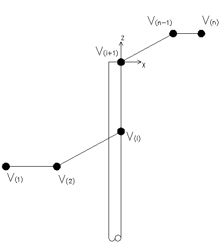
Seeing the importance that the insertion of the data in terms of coordinates of the vertices has, some specifications must be made.
•The reference system with regard to which the coordinates of the vertices are defined has always its origin in correspondence of the head of the bulkhead;
•The succession of the vertices must be entered in the downstream-upstream order.
You can refer to the following figure:
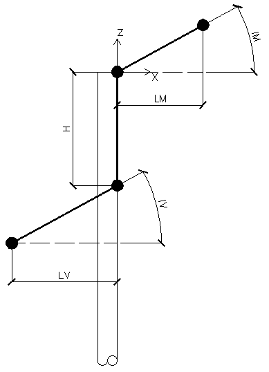
We report, for the sake of completeness, a guide figure for the insertion of the geometrical data by angles and distances.
© GeoStru