The software offers the possibility to take into consideration the presence of possible distributed loads, considered as Lines, Strips or Uniform Loads.
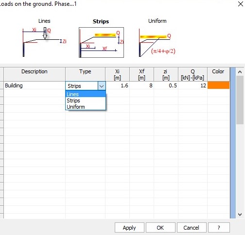
The data to be entered for a correct definition of a load is the following:
•Description: Identifies the load; data necessary for the identification of the action in the load combinations.
•Type: Choose amongst load lines, load strips and uniformly distributed load.
•xi: It is the abscissa starting from which the load starts acting. In case of load lines, it is the abscissa which defines the application of the load line; it is expressed in m.
•xf: Data required if load strips or uniform loads are defined. It is the final abscissa of the load (so, it defines the extension of the load); it is expressed in m.
•zi: Depth expressed in m, currently only having graphic value, therefore the increase of stress induced by the overload is still evaluated starting from the head of the bulkhead.
•Q: Load - expressed in kN (in case of load line) or in kN/m² (in case of strip and uniform load).
•Color: Assignation of the color to be used for the display of the load strip.
N.B. The loads are distributed per linear meter in the longitudinal direction.
For the interpretation of the different types of load, it may be useful to have a look at the following figure:
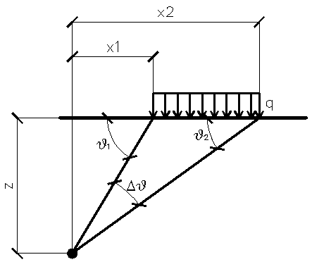
Orthogonal load strips
For load strips, the distribution of the stresses is estimated according to the depth z.
A partially distributed load with an initial abscissa x1 and a final abscissa x2 generates a diagram of pressures upon the wall whose values have been determined according to the TERZAGHI formulation, which expresses the pressure at a generic z depth, as follows:
![]()
Δϑ = ϑ1-ϑ2;
A = sin(2ϑ1)-sin(2ϑ2)
B = cos(2ϑ1)-cos(2ϑ2)
ϑ1 = arctg(z/x1)
ϑ2 = arctg(z/x2)
By integration, the resultant and the relevant arm will be obtained.
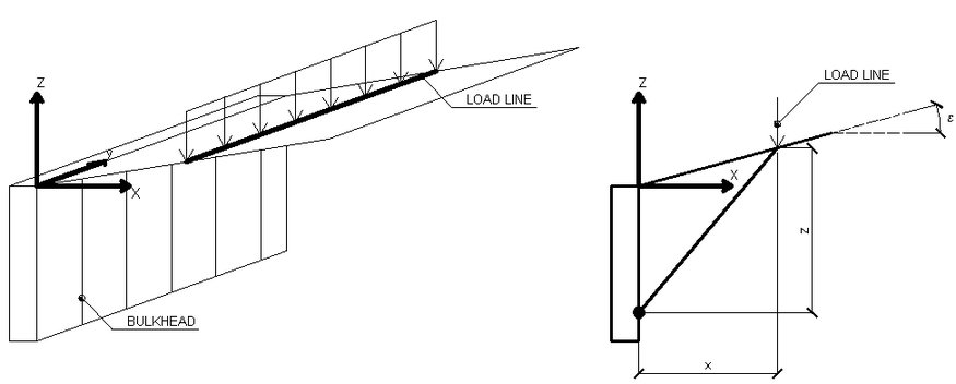
Schematization of the load lines
In this case too, as for the load strips, the distribution of the stresses is estimated according to the depth z. The load lines generate an increase in the pressures upon the wall, which, according to BOUSSINESQ – at the depth z – can be expressed as follows:
![]()
![]()
Where the symbols have the following meaning:
V = Intensity of the load expressed in [F/L]
X = Distance, in horizontal projection, of the point of application of the load from the wall
If the action plane is inclined by ε, the reference system (x,z) is rotated in (X,Z) through the following transformation:
![]()
A load Q, uniformly distributed on the ground surface induces constant pressures equal to:
![]()
By integrating the stress indicated in the above formula, we obtain the total thrust due to overload:
![]()
With the point of application to H/2 (being the stress distribution constant). In the above formulas the symbols have the following meaning:
β = Inclination of the inner wall to the horizontal plane passing through the foot
ε = Inclination of the ground surface to the horizontal - positive if counterclockwise
Ka = Coefficient of active pressure calculated in the previous paragraph.
N.B. The uniform load is distributed automatically by the head of the bulkhead across the width of the failure wedge.
© GeoStru