Biaxial bending with axial force refers to general section and rectangular section of columns.
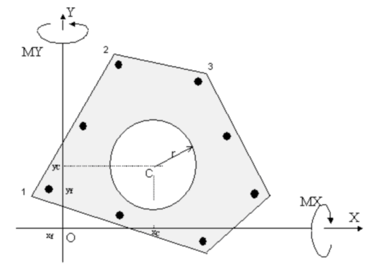
A general section (as that depicted in the below figure) consistes in one or more concrete polygonal regions and any number of bar anyway arranged. Concrete geometrical data and bars have a general reference system O,X,Y. Positive bending moment are showed in the figure. N assigned normal force (positive if compressive) is applied in the centroid of concrete regions. Bending design moment can be refered to O,X,Y axes or C,x,y principal inertia axes.
In calculations performed by the program internal normal force N is applied in the origin O and MX,MY to X,Y axes.
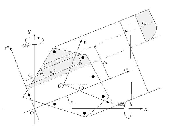
Scheme of integration of stesses in biaxial bending
In the above figure is showed the scheme of integration of stresses referred to a generic position of neutral axis with the same inclination α of x* axes which belongs to a rotated reference system O,x*,y*. The numerical integration is performed with:
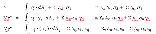
where, with reference to the generic discrete strip i of the figure:
Aci = (xci2- xci1) ⋅ Δy
xci = (xci2 + xci1) / 2
The integration results Mx*, My* are then referred to B, ξ, ,η principal inertia system (to compare the internal forced with the design ones):
Mξ = Mx* cos θ + My* sin θ + N yR
Mη = -Mx* sin θ + My* cos θ - N xR
where xR, yR are the coordinates of origin O referred to principal axes of inertia.
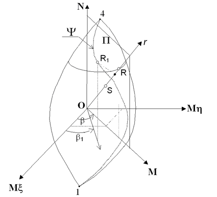
Three-dimensional interaction domain N-Mξ-Mη
As you can see in the above figure, the generic design forces S⎨NSd, MηSd, MξSd⎬ has three components to compare, in a definite measure direction r, with the correspondent strength forces R⎨NRd, MηRd, MξRd⎬ obtained by the intersection of the straight line r with the surface of interaction (border of 3-d domain). To each point of this surface correspond a strain configuration of the section with a failure of concrete or steel. In particular the cusp points 1 correspond to the max tension strain (εud) at null curvature and 4 to the min compressive strain (εcd) at null curvature. For each direction α of the neutral axis we can obtain the same possible strain distribution at ultimate limit state seen in uniaxial bending with characteristic intermediate point 2-3. The ultimate border line 1-2-3-4 seen in uniaxial bending here become (performing the previous numerical integrations) a three-dimansional line ψ (from 1-4 in above figure). Varying the angle α (i.e. neutral axis direction) from 0 to 2 π the set of all the curves ψ constitute the entire interaction surface.
|
© 2020 Geostru