Lumped Mass model
The assumptions of the Lumped Mass model are:
1.plan outline, the slope profile similar to a broken line consisting of straight line segments
2. point boulder and neglectable air resistance
In this case the trajectory of the boulder can be determined using the equations of
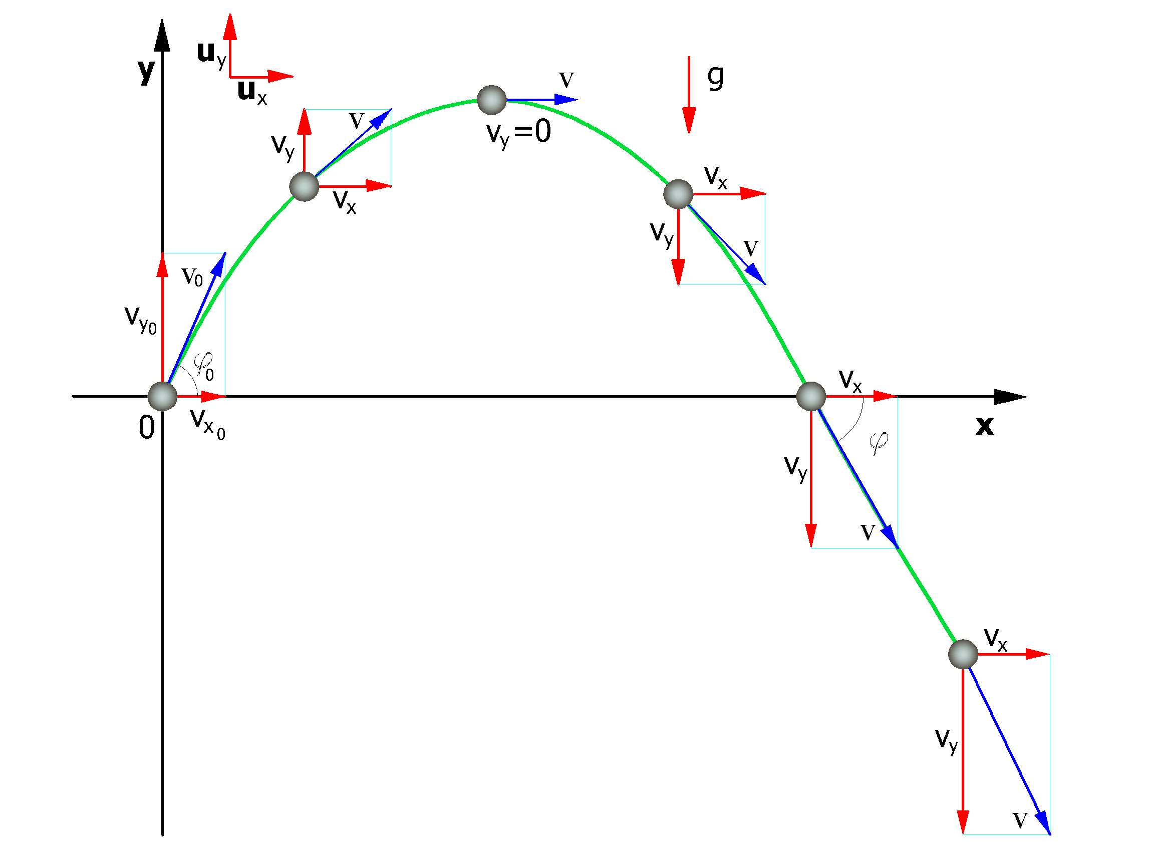
The motion is characterized by a constant acceleration a=g=-guy and the initial conditions are v=v0 at time t=0, moment of launch.
From the definition of acceleration in plane motion we obtain the following relation:
as
![]()
the velocities of the motion projected on the axes are:
![]()
![]()
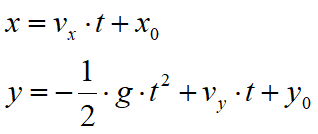
Referring to the same system of orthogonal Cartesian axes, the timing laws of the projected motions are:
|
(1) |
where:
vx |
horizontal component of the velocity of the boulder |
vy |
vertical component of the velocity of the boulder |
t |
time |
g |
acceleration of gravity |
x0 |
abscissa of the point where the boulder is detached from the slope or impacts in the falling motion |
y0 |
ordinate of the point where the boulder is detached from the slope or impacts in the falling motion |
Along the x-axis the motion is uniform while along the y axis the motion is uniformly accelerated.
In this way the trajectory of the boulder motion is composed of a series of parabolas drawn between the point at which the detach takes place and the point at which the boulder collides on the slope for the first time, in the initial phase of motion, and between two successive impact points on the slope, or at the foot of the slope, later, to the stop point.
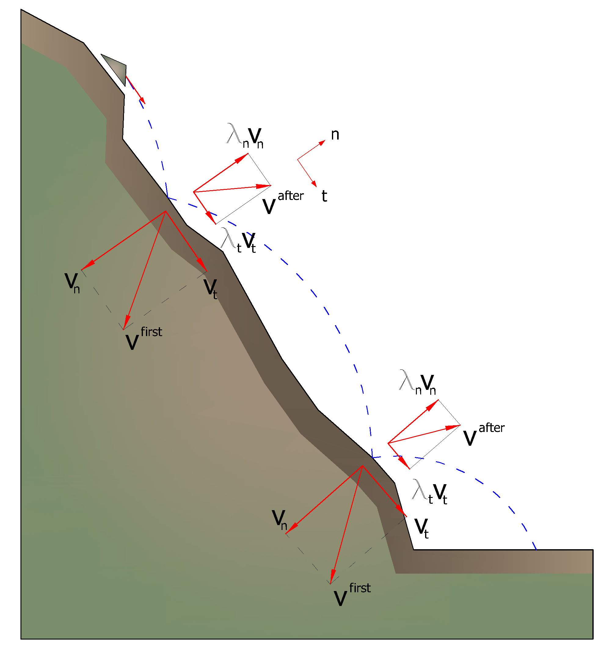
The coordinates of the impact points and velocity components are determined by solving the system between the equation (1) and the equation of the straight line representing the profile of the slope.
In practice we proceed from the point where the detachment of the boulder occurs and we resolve this system of equations considering in turn the different equations of the straight lines that contain the successive segments of the broken line up to finding the coordinates of a point, impact point, that belongs to the parabola that represents the trajectory and falls within of one of the segments of the broken line and is therefore also a point of the slope.
This point is the first impact point of the boulder on the slope. The procedure is repeated from that point to determine the next arc of the trajectory and a new impact point.
The loss of kinetic energy due to friction and impacts can be modeled by reducing the velocity of the falling boulder whenever this impacts on the slope.
In particular, indicating with vn and vt the components (normal and tangential) of the velocity before impact, after the impact v'n, v't can be calculated using the relationship:
![]()
Rn and Rt are the restitution coefficients, variable in the range 0-1.
|
© GeoStru