This window enables entry of parameters required for Finite Elements Method in structural analysis. It is only available if in Structural computation was selected in the Global Data window. The window is made up by three segments: ‘Analysis Options’, ‘Loads’, and ‘Boundary conditions’. In Analysis Options the following variables should be determined:
Max. linear soil displacement (m)
Enter maximum linear soil displacement in metres.This value embodies a boundary condition for nodal reactions of the springs by which the terrain is represented.
Analysis Type
Select linear or non linear from the dropdown list. The two types refer to the terrain deformation in the area selected by the user.
Max. number iterations
Terminator value for iteration process in determination of displacement matrix and stresses.
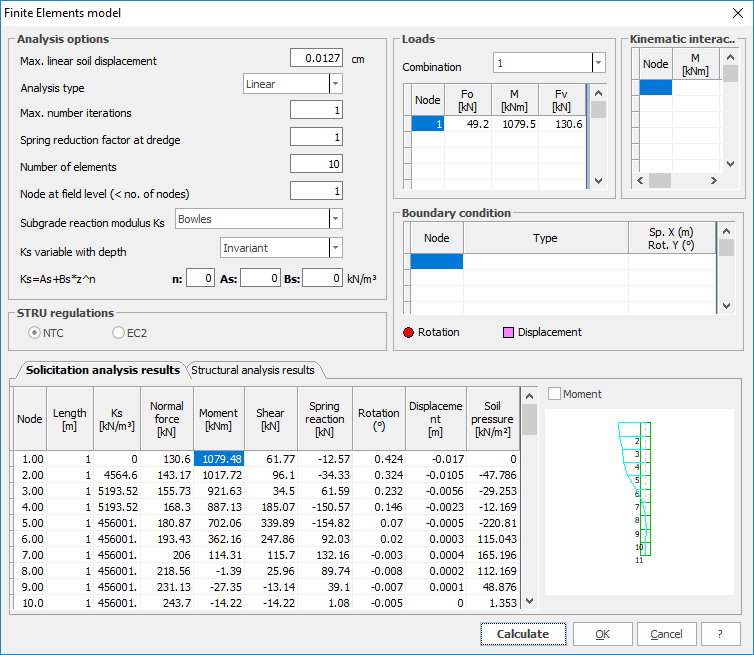
Spring reductn. factor at dredge line
Specify factor by which spring rigidity at the bottom of excavation should be reduced. This is useful to take account of soil recast during the insertion of pile or minipile, If no account is to be given to this effect, enter the value 1.
Number of elements
Enter number of elements into which the pile (or minipile) is to be subdivided for the determination of stress and deformation.
Node at field lvl. (< no. of nodes)
Give node ordinal number for node at excavation dredge line. (Nodes are numbered from top downwards). This number will necessarily be less than the number of elements above.
Subgrade reaction modulus Ks
Select from the two alternatives (Chiarugi-Maia/ Bowles) in the drop down list the method for the computation of the subgrade reaction modulus. See also Minipile in Operation.
Ks variable with depth
Select either whether subgrade reaction modulus should be varied with depth or held constant. In Loads a table is presented in which load(s) may be declared. It contains the following columns:
Node
Node number to which the load is applied. (Nodes are numbered from top downwards).
Fo
Enter Horizontal force value.
M
Enter couple value.
Fv
Enter Vertical force value.
In Boundary conditions a table is presented in which node condition(s) may be declared. It contains the following columns:
Node
Node number to which the condition applies. (Nodes are numbered from top downwards).
Type
Select from list either Displacement or Rotation to be applied.
Sp. X(m) Rot Y (º)
Enter either displacement in metres or rotation angle depending on type chosen in previous cell.
Note: Conventions, recalled in tip text which appears when cursor is in one of the columns, whereby Horizontal forces (Fo) are given as +ve when acting right to left; Vertical forces (Fv) are given as +ve when acting downwards; Couple (M) or rotations are given as +ve when clockwise.
© GeoStru