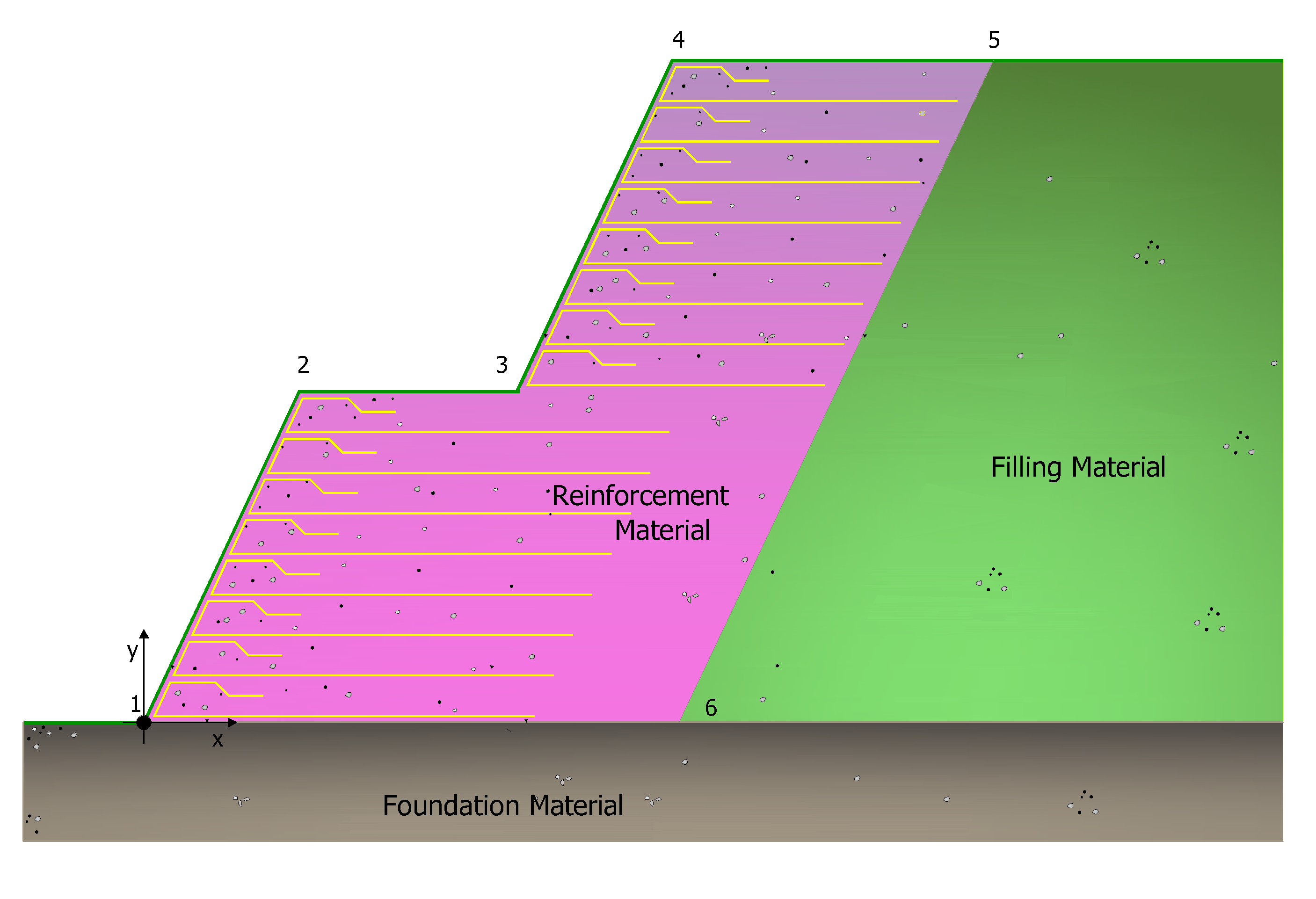
The reinforced earth profile is defined by X, Y coordinates referred to a local reference system whose origin is the lower vertex. The profile should be closed as seen in the figure below, the vertices of the reinforced earth 1,2,3,4,5,6 close the reinforcement polygon shown in pink.

The polygon of the reinforcements must be closed the first vertex must have coordinates (0,0).
|
The polygon may be defined by points, inserting manually the coordinates X, Y in the table, or by automatic generation, in which case the geometric profile can be either a constant slope or a terraced slope.
If automatic generation is chosen, the required input data is:
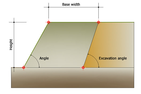
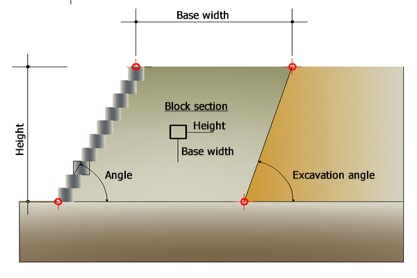
- the reinforcement angle, internal to the polygon, the angle that the profile of the slope forms with the horizontal
- the height and the width of the reinforcement polygon

Geometry automatic generation, input data
The automatic generation mode "Terracing" is performed by the software giving the size of the blocks by default or by using those that are assigned by the user in "Blocks" section.

In "Geometry" are assigned the geometrical dimensions of the foundation. Confirm each input with "Apply".
To delete the input select all numerical values in the table and press Del key from your keyboard, or right click and choose "Delete all".
The command "Import DXF" offers the possibility to import the profile of the reinforcement, a necessary condition. The profile is defined by an open polyline increasing from left to right.
If the user has the profile coordinates of a spreadsheet they can be copied and pasted in the input table.
The meaning of the flags in the "Use" column is that the corresponding point has been used to "hook" a block.
|
© GeoStru