The analysis of the bulkhead is organized by analysis phases and load combinations. In particular, it is possible to define more analysis phases, which differ from one another on the basis of the input data. For each analysis phase, it is possible to define more load combinations. The environment that manages the analysis of the bulkhead and related phases and load combinations is the following:
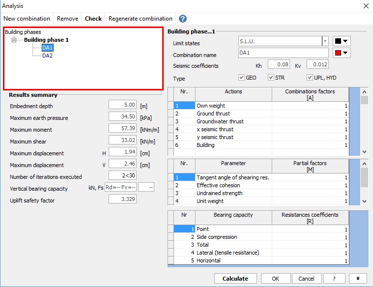
The main considerations to be made as regards the analysis procedure are the following:
•It is possible to analyze more constructive phases, and for each of them to analyze more load combinations. (To add a new load combination just click on New combination button, or click Remove to delete a combination previously selected. Click Regenerate combination to turn back to default combination.)
•To each load combination, it is possible to associate the type of checks to be carried out and consequently whether to carry out checks to ultimate limit states (SLU) or serviceability limit states (SLE), and select the type GEO (geotechnical) STR (structural) and UPL, HYD (hydraulic).
•It is possible to manage the partial amplification factors for loads as well as the partial reduction factors for the the geotechnical parameters and for the resistances.
•The seismic coefficients kh and kv to be associated to the seismic combinations can be calculated automatically or inserted manually.
In order to carry out the analysis of the bulkhead (all phases and combinations) it is necessary to click on the Calculate button.
N.B. The combination coefficients and synthesis of the results reported in the Analysis dialog box refer to the combination that the user selects in the box shown in red in the previous image.
|
Summary of results
For each construction phase and for every combination is displayed a summary of the results, in particular, will be given the following values:
oEmbedment depth
oMaximum earth pressure
oMaximum moment
oMaximum shear
oMaximum horizontal displacement H based on which the user will determine if the value is acceptable to the bulkhead in question (the result is obtained in case of F.E.M. analysis)
oMaximum vertical displacement V (the result is obtained in case of F.E.M. analysis)
oNumber of iterations performed (the result is obtained in case of F.E.M. analysis)
oVertical bearing capacity with safety factor FS (not determined for the generic sections of A, E, I, G input)
Results anchors and struts
In case of anchors and / or struts will also be shown the results for:
o Name given to the anchor in the input phase
o Q: bearing capacity, in kN
o R: reaction of the anchor, in kN
o FS: safety factor calculated as:
FS=Q/R
Check satisfied for FS> 1.
N.B. The program calculates the resistance of the anchor considering the anchored part (bulb length), while the value of the reaction is determined according to the length of the free part.
oName given to the strut in the input phase
oReaction of the strut, in kN
oSafety factor calculated as:
FS=(Area * Fyd) / Reaction of the strut
The results are related to a linear meter of the bulkhead.
Additional results
By clicking the button highlighted in yellow in the image below, additional results are displayed:
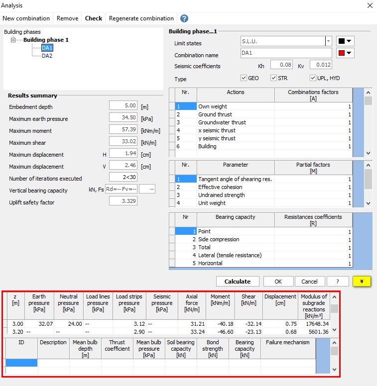
The first table shows the values of the earth pressure, neutral pressure, the pressure due to load lines, the seismic pressure (see. Pressures diagrams), stress (see. Stress diagrams) and the subgrade reaction module for all the elements in which the bulkhead is discretized. If the modulus of subgrade reaction is not assigned by the user, will be determined automatically by the software.
The second table refers to the verification of the anchors and reports the average depths of the bulb, the thrust coefficient, the average pressure of the bulb, the bearing capacity of the soil, bond strength, the bearing capacity of the anchor and the failure mechanism.
© GeoStru