Eurocode 8
3 GROUND CONDITIONS AND SEISMIC ACTION (EC8 - part 1)
3.1 Ground conditions
3.1.2 Identification of ground types
- Ground types A, B, C, D, and E, described by the stratigraphic profiles and parameters given in Table 3.1 and described hereafter, may be used to account for the influence of local ground conditions on the seismic action. This may also be done by additionally taking into account the influence of deep geology on the seismic action.
Note: The ground classification scheme accounting for deep geology for use in a country may be specified in its National Annex, including the values of the parameters S, TB, TC and TD defining the horizontal and vertical elastic response spectra in accordance with 3.2.2.2 and 3.2.2.3.
| A | Rock or other rock-like geological
formation, including at most 5 m of
weaker material at the surface. | >800 | | |
| B | Deposits of very dense sand, gravel, or very stiff clay, at least several tens of meters in thickness, characterized by a gradual increase of mechanical properties with depth. | 360-800 | >50 | >250 |
| C | Deep deposits of dense or medium-dense sand, gravel or stiff clay with
thickness from several tens to many
hundreds of meters. | 180-360 | 15-50 | 70-250 |
| D | Deposits of loose-to-medium
cohesionless soil (with or without some soft cohesive layers), or of
predominantly soft-to-firm cohesive
soil. | <180 | <15 | <70 |
| E | A soil profile consisting of a surface
alluvium layer with v s values of type C or D and thickness varying between about 5 m and 20 m, underlain by stiffer material with v s > 800 m/s. | | | |
| S1 | Deposits consisting, or containing a
layer at least 10 m thick, of soft
clays/silts with a high plasticity index (PI > 40) and high water content | <100
(indicative) | | 10-20 |
| S2 | Deposits of liquefiable soils, of
sensitive clays, or any other soil profile not included in types A – E or S 1 | | | |
Prospect 3.1-Ground types
| (3.1) | |
|---|---|
where hi and vi denote the thickness (in meters) and shear-wave velocity (at a shear strain level of 10–5 or less) of the i-th formation or layer, in a total of N, existing in the top 30 m.
Note: Special attention should be paid if the deposit is of ground type S1 . Such soils typically have very low values of vs , low internal damping and an abnormally extended range of linear behaviour and can therefore produce anomalous seismic site amplification and soil-structure interaction effects (see EN 1998-5:2004, Section 6). In this case, a special study to define the seismic action should be carried out, in order to establish the dependence of the response
spectrum on the thickness and vs value of the soft clay/silt layer and on the stiffness contrast between this layer and the underlying materials.
3.2 Seismic action
3.2.1 Seismic zones
Note: The reference peak ground acceleration on type A ground, agR , for use in a country or parts of the country, may be derived from zonation maps found in its National Annex.
Note: The selection of the categories of structures, ground types and seismic zones in a country for which the provisions of low seismicity apply may be found in its National Annex. It is recommended to consider as low seismicity cases either those in which the design ground acceleration on type A ground, ag , is not greater than 0,08g (0,78 m/s2), or those where the product ag x S is not greater than 0,1 g (0,98 m/s2). The selection of whether the value of ag , or that of the product ag x S will be used in a country to define the threshold for low seismicity cases, may be found in its National Annex.
Note: The selection of the categories of structures, ground types and seismic zones in a country for which the EN 1998 provisions need not be observed (cases of very low seismicity) may be found in its National Annex. It is recommended to consider as very low seismicity cases either those in which the design ground acceleration on type A ground, ag , is not greater than 0,04g (0,39 m/s2), or those where the product ag x S is not greater than 0,05g (0,49 m/s2). The selection of whether the value of ag , or that of the product ag x S will be used in a country to define the threshold for very low seismicity cases, can be found in its National Annex.
3.2.2 Basic representation of the seismic action
3.2.2.1 General
3.2.2.2 Horizontal elastic response spectrum
where:
Se(T )is the elastic response spectrum;
Tis the vibration period of a linear single-degree-of-freedom system;
agis the design ground acceleration on type A ground (ag =γIagR);
TB is the lower limit of the period of the constant spectral acceleration branch;
TC is the upper limit of the period of the constant spectral acceleration branch;
TDis the value defining the beginning of the constant displacement response range of the spectrum;
S is the soil factor;
η is the damping correction factor with a reference value of η= 1for 5% viscous damping, see (3) of this subclause.
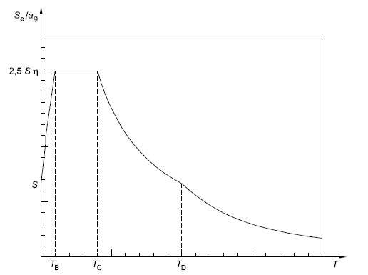
Figure 3.1 - Shape of the elastic response spectrum
Note 1: The values to be ascribed to TB , TC , TD and S for each ground type and type (shape) of spectrum to be used in a country may be found in its National Annex. If deep geology is not accounted for (see 3.1.2(1) ), the recommended choice is the use of two types of spectra: Type 1 and Type 2. If the earthquakes that contribute most to the seismic hazard defined for the site for the purpose of probabilistic hazard assessment have a surface-wave magnitude, Ms , not greater than 5,5, it is recommended that the Type 2 spectrum is adopted. For the five ground types A, B, C, D and E the recommended values of the parameters S, TB , TC and TD are given in Table 3.2 for the Type 1 Spectrum and in Table 3.3 for the Type 2 Spectrum. Figure 3.2 and Figure 3.3 show
the shapes of the recommended Type 1 and Type 2 spectra, respectively, normalized by a g, for 5% damping. Different spectra may be defined in the National Annex, if deep geology is accounted for.
| A | 1,0 | 0,15 | 0,4 | 2,0 | | B | 1,2 | 0,15 | 0,5 | 2,0 | | C | 1,15 | 0,20 | 0,6 | 2,0 | | D | 1,35 | 0,20 | 0,8 | 2,0 | | E | 1,4 | 0,15 | 0,15 | 2,0 |
Table 3.2 - Values of the parameters describing the recommended Type 1 elastic response spectra
| A | 1,0 | 0,05 | 0,25 | 1,2 | | B | 1,35 | 0,05 | 0,25 | 1,2 | | C | 1,5 | 0,10 | 0,25 | 1,2 | | D | 1,8 | 0,10 | 0,30 | 1,2 | | E | 1,6 | 0,05 | 0,25 | 1,2 |
Table 3.3 - Values of the parameters describing the recommended Type 2 elastic response spectra
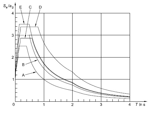
Figure 3.2 - Recommended Type 1 elastic response spectra for ground types A to E (5% damping)
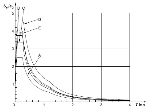
Figure 3.3 - Recommended Type 2 elastic response spectra for ground types A to E (5% damping)
Note 2: For ground types S1 and S2, special studies should provide the corresponding values of S, TB , TC and TD.
| (3.6) | |
|---|---|
where:
x is the viscous damping ratio of the structure, expressed as a percentage.
| (3.7) | |
|---|---|
Note: For the Type 1 elastic response spectrum referred to in Note 1 to 3.2.2.2(2)P, such a definition is presented in Informative Annex A in terms of the displacement response spectrum. For periods longer than 4,0 s, the elastic acceleration response spectrum may be derived from the elastic displacement response spectrum by inverting expression (3.7).
3.2.2.3 Vertical elastic response spectrum
Note: The values to be ascribed to TB , TC , TD and avg for each type (shape) of vertical spectrum to be used in a country may be found in its National Annex. The recommended choice is the use of two types of vertical spectra: Type 1 and Type 2. As for the spectra defining the horizontal components of the seismic action, if the earthquakes that contribute most to the seismic hazard defined for the site for the purpose of probabilistic hazard assessment have a surface-wave magnitude, Ms , not greater than 5,5, it is recommended that the Type 2 spectrum is adopted. For the five ground types A, B, C, D and E the recommended values of the parameters describing the vertical spectra are given in Table 3.4. These recommended values do not apply for special ground types S1 and S2 .
| Type 1 | 0,90 | 0,05 | 0,15 | 1,0 | | Type 2 | 0,45 | 0,05 | 0,15 | 1,0 |
Table 3.4 - Recommended values of parameters describing the vertical elastic response spectra
where:
ag, S, TC e TD are as defined in 3.2.2.2;
Sd(T ) is the design spectrum;
q is the behaviour factor;
β is the lower bound factor for the horizontal design spectrum.
Note: The value to be ascribed to ß for use in a country can be found in its National Annex. The recommended value for β is 0,2.
3.2.3 Alternative representations of the seismic action
3.2.3.1 Time - history representation
3.2.3.1.1 General
3.2.3.1.2 Artificial accelerograms
a) a minimum of 3 accelerograms should be used;
b) the mean of the zero period spectral response acceleration values (calculated from the individual time histories) should not be smaller than the value of agS for the site in question.
c) in the range of periods between 0,2T1 and 2T1 , where T1 is the fundamental period of the structure in the direction where the accelerogram will be applied; no value of the mean 5% damping elastic spectrum, calculated from all time histories, should be less than 90% of the corresponding value of the 5% damping elastic response spectrum.
3.2.3.1.3 Recorded or simulated accelerograms
3.2.3.2 Spatial model of the seismic action
3.2.4 Combinations of the seismic action with other actions
| (3.17) | |
|---|---|
where:
YE,i is the combination coefficient for variable action i (see 4.2.4).
4.1.3 Slope stability
4.1.3.3 Methods of analysis (EC 8-part 5)
FH = 0,5 a S W
FV = ± 0,5 FH if the ratio avg/ag is greater than 0,6
FV = ± 0,33 FH if the ratio avg/ag is not greater than 0,6.
Where:
ais the ratio of the design ground acceleration on type A ground, ag , to the acceleration of gravity g;
avg is the design ground acceleration in the vertical direction;
ag is the design ground acceleration for type A ground;
S is the soil parameter of EN 1998-1:2004, 3.2.2.2;
W is the weight of the sliding mass.
A topographic amplification factor for a g shall be taken into account according to 4.1.3.2 (2).
-
A limit state condition shall then be checked for the least safe potential slip surface.
-
The serviceability limit state condition may be checked by calculating the permanent displacement of the sliding mass by using a simplified dynamic model consisting of a rigid block sliding against a friction force on the slope. In this model the seismic action should be a time history representation in accordance with 2.2 and based on the design acceleration without reductions.
-
Simplified methods, such as the pseudo-static simplified methods mentioned in (3) to (6) in this subclause, shall not be used for soils capable of developing high pore water pressures or significant degradation of stiffness under cyclic loading.
-
The pore pressure increment should be evaluated using appropriate tests. In the absence of such tests, and for the purpose of preliminary design, it may be estimated through empirical correlations.