Construction phases
SPW allows the insertion of multiple construction phases.
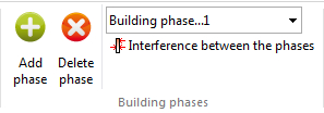
Add phase: Allows to enter an analysis phase at increasing depths.
Delete phase: Deletes the current analysis phase.
Interference between the phases: Allows to have interference between the phases. Initializes each phase according to the interaction with the previous phase. Even in the absence of anchors can be noticed a difference in stress between the phases, due to the interaction of the stress field of the current phase compared to the previous one.
The pressure diagrams will be related to the phase stress field. By activating this command, will be created automatically load conditions at the current phase based on the previous one.
If there is a difference between the phases of displacement, will activate the passive rods.
In the analysis by phases is not possible to automatically calculate the depth of embedment using finite elements.
N.B. If the command Interference between the phases is not active, in the calculation process there is no interference between the phases.
Application case – Wall with strut installed in phase 2
Analysis sequence on model 1091calc-Paratia.spwx with
Interference between the phases option enabled and equivalent
pre-stress automatically applied to the strut installed in phase 2.
When a strut is installed on a wall already deformed by \(\delta_0\), the FEM solver automatically applies the equivalent pre-stress \(k \cdot \delta_0\) at the connection node, so that the support reaction follows the physical law:
At installation the reaction is zero (the strut is placed on the deformed configuration without preload); in the following phases the strut stiffness only resists the increment of displacement.
Animated summary of the calculation sequence (loop, ~2 s per phase).
Phase 1 – Initial excavation, free wall
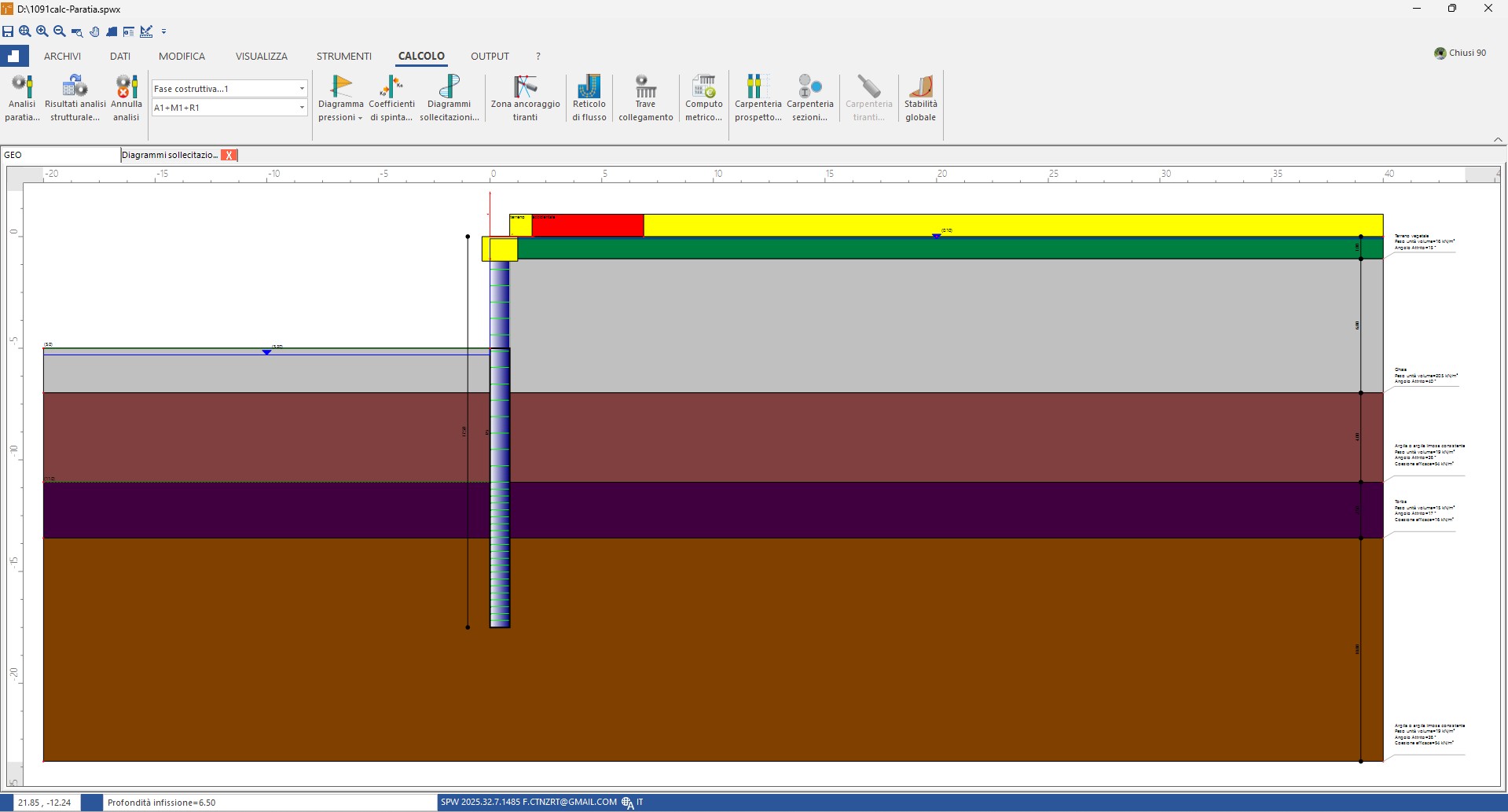
Stratigraphy and wall geometry in phase 1: cantilever wall, no support.
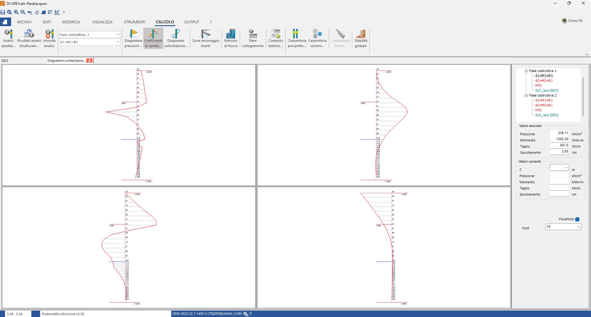
Phase 1 results — combination A1+M1+R1: max pressure 336.11 kN/m², bending moment 1,205.39 kNm/m, shear 347.5 kN/m, maximum displacement \(\delta_0 = 2.85\) cm at the top. This is the "inherited" value the strut will find at installation.
Phase 2 – Deeper excavation with strut installed at the top
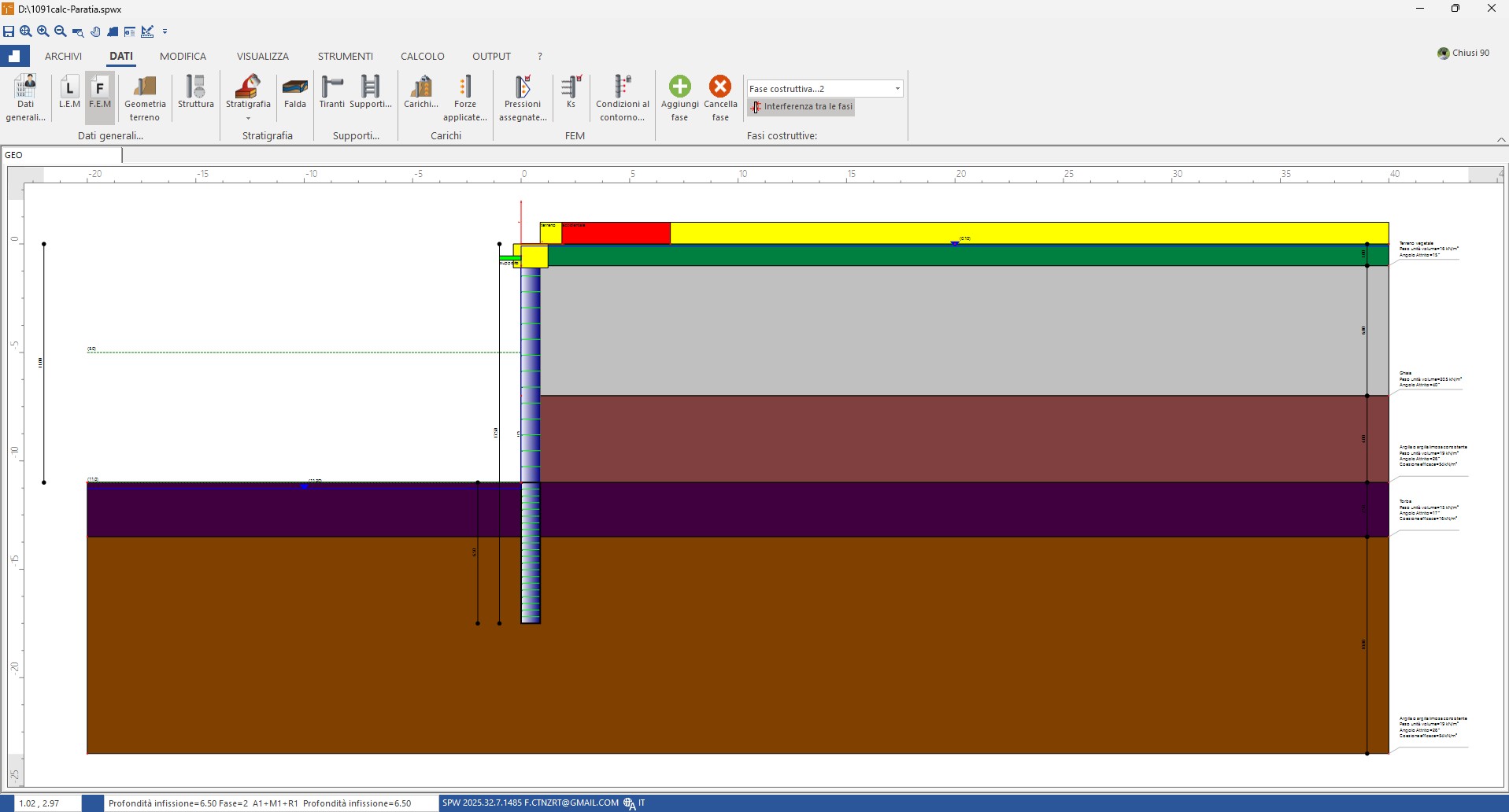
Phase 2 setup: deeper excavation and strut at the top just installed. The Interference between the phases option is active (top-right panel): the FEM solver automatically applies the equivalent pre-stress \(k \cdot \delta_0\) at the strut connection node, so that its initial reaction on the increment is zero.
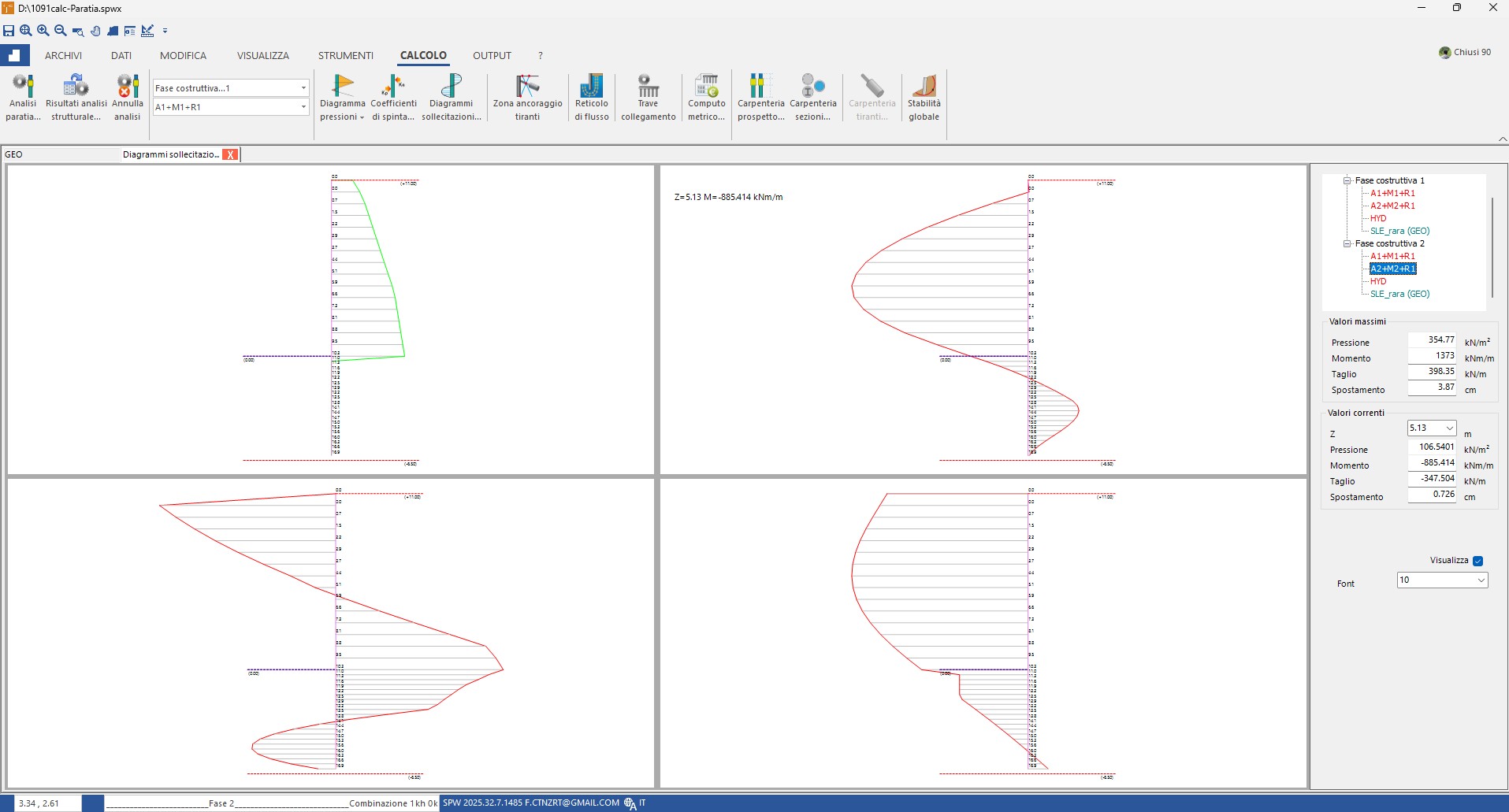
Phase 2 results — combination A2+M2+R1: max pressure 354.77 kN/m², bending moment 1,373 kNm/m, shear 398.35 kN/m, maximum displacement \(\delta = 3.87\) cm. The top is "locked" near the inherited value \(\delta_0\) and the strut reaction is the physical reaction \(F = k \cdot (\delta - \delta_0)\), consistent with sizing.