Last typology that you can select in the General Data window is the SLS deflection calculation of a single isostatic beam for the verification of limit state of deformation.
The beam can be hyperstatic as belonging to a frame, but solving the frame, for the SLS combination of interest (usually quasi-permanent), we make the beam isostatic applying two bending moments at the end (see main window in below figure). Alternatively the beam may be a cantilever.
In general maximal sag of a beam must not exceeds span/250 if subject to a quasi-permanent loads. Deflection after construction that could damage adjacent part of the structure must be limited to span/500.
You can directly check (no check is performed by the program) the limit state of deformation comparing the above limit values (or the limit value that you choose) with a calculated deflection performed by the program according to the most rigorous method described in §7.4.3(7) EC2 by double integration of the differential equation of the bending and computing curvatures at frequent section along the member.
The calculation take in account cracking, creep, aging and shrinkage as mentioned in the topic Limitation of Deformation.
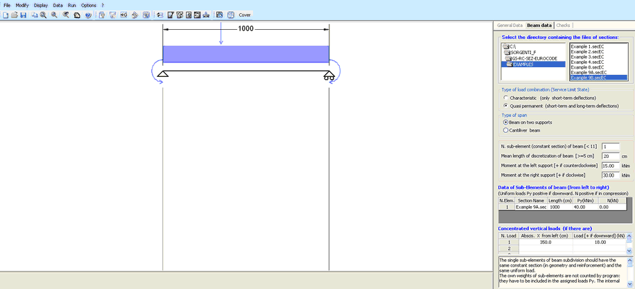
Beam can be assigned as consisting as one or more sub-elements: each sub-element is characterized by a constant section (as geometry and reinforcement) and a distributed load acting on it. Two sub-element may be different only for different placing of longitudinal bars or for different distributed loads. Before of this input it is necessary to input ad save with a different name the above section that define the different sub-element (even a single). The section to assign may be predefined or general but with uniaxial bending forces and must be saved in a single directory. Creep and shrinkage coefficients assigned (in Materials library) to each section are taken in account in the deflections calculation of the beam.
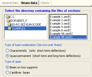
The input begin with the selection of the directory (no selection of file) in the above dialog box. Then you must define the type of load combination (Characteristic only for short term deflections or quasi-permanent for short and long term deflections). The selection of the type of span complete this first part of input.
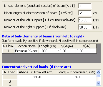
The data of each sub-element are (in this example there is only one):
- Section Name: to select in the first column of the grid (in this column are present all the file *.secEU within the directory selected before)
- Lengh [cm]: of each sub-element (the sum of all sub-elements is the span of the beam)
- Py [kN/m]: if the uniformly distributed load included self-weight.
- N [kN]: Axial force (acting in the centroid of all sections). May be useful for evaluation of viscous shortening of columns in a multi-storey building.
Eventual concentrated vertical loads can be assigned (as in above grid) with their abscissa [cm] from left support and value [kN].
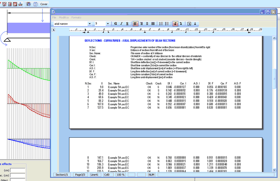
RESULTS
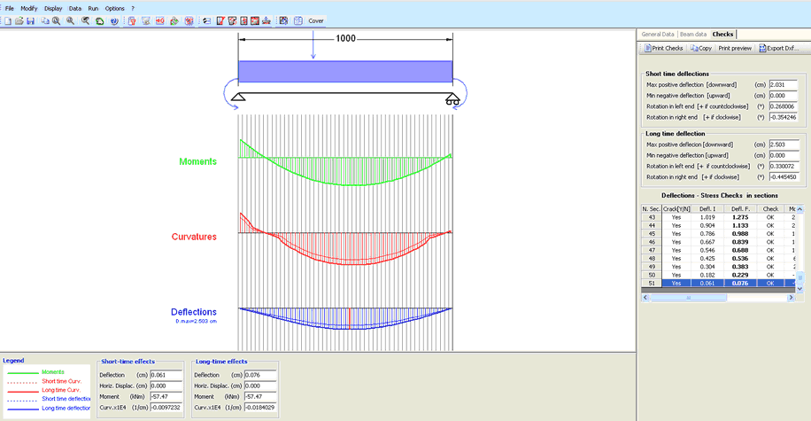
Moving the mouse along the beam length you can read the single section results in the information window (bottom of the screen).
Deflection results are distinct in short time (only cracking if it occurs and no rheological coefficient applied) and long time deflection. Stress check is also performed by the program.
![]()
The above command Tab bar contains the usual tools seen in the other typology.
After Print command the printing output is:
|
© 2020 Geostru