Selecting "Forces" Tab the program shows the underlying dialog windows that make possible the input of load combination forces (up to 60 for ULS and SLS).
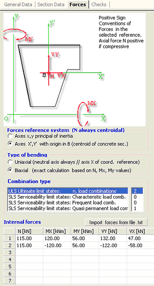
This window automatically varies according to the typology of the section. The two figures below show the windows for a predefined section (the left one) and for a general section (the right one).
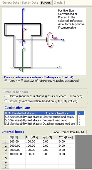
Force reference system (N is always applied at the centroid of the concrete section)
For general sections (right figure) are provided two reference systems (x,y axes principal of inertia or axes X',Y' parallels to X,Y coordinates axes); type of bending and shear can be uniaxial (X' axis is always parallel to X) or biaxial. Internal forces MX,MY are bending moments, VX,VY are shear forces, N is axial force: sign conventions are showed in the scheme placed in the upper part of the figure.
For predefined sections (left figure)reference system can be only that parallel to X,Y coordinate axes and bending moments and shear forces cam be only uniaxial. Internal force Mx is the bending moment, Vy is the shear force, N is axial force and T is the torsional force: sign conventions are showed in the scheme placed in the upper part of the figure.
For rectangular sections of columns and for rectangular sections of walls general coordinates system overlaps with local system x,y (axes principal of inertia)
Type of bending
For predefined sections the type of bending is only uniaxial. For rectangular sections of columns and walls is only biaxial.
Only for general section it is possible the choose between uniaxial (neutral axis forced to be parallel o X axis) or biaxial bending (and shear).
Combination type
Selecting in this box one of the four type of load combinations (the first relates to ultimate limit states the subsequent three to serviceability limit states) are shown, in the underlying grid, the corresponding internal forces assigned or to assign. It is required to assign at least one ULS combination.
Internal forces
In this grid you can enter, in the pertinent columns, the internal forces acting on the section. The type of forces vary depending on the type of section and of the reference system assumed above.
You can assign forces importing their values by a text file previously prepared (see Import forces from text file).
You can also assign forces pasting with the mouse columns of values from a different grid (excel etc).
|
© 2020 Geostru